HP GbE2c HP GbE2c Ethernet Blade Switch for c-Class BladeSystem ISCLI Referenc - Page 128
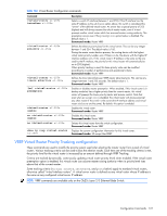
VRRP Virtual Router Group configuration, show ip vrrp virtual-router
 |
UPC - 808736802215
View all HP GbE2c manuals
Add to My Manuals
Save this manual to your list of manuals |
Page 128 highlights
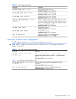
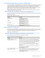
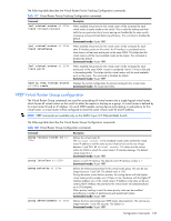
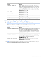
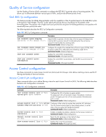
The following table describes the Virtual Router Priority Tracking Configuration commands. Table 147 Virtual Router Priority Tracking Configuration commands Command [no] virtual-router track virtual-routers [no] virtual-router track interfaces [no] virtual-router track ports show ip vrrp virtual-router track Description When enabled, the priority for this virtual router will be increased for each virtual router in master mode on this switch. This is useful for making sure that traffic for any particular client/server pairing are handled by the same switch, increasing routing and load balancing efficiency. This command is disabled by default. Command mode: Router VRRP When enabled, the priority for this virtual router will be increased for each other IP interface active on this switch. An IP interface is considered active when there is at least one active port on the same VLAN. This helps elect the virtual routers with the most available routes as the master. This command is disabled by default. Command mode: Router VRRP When enabled, the priority for this virtual router will be increased for each active port on the same VLAN. A port is considered "active" if it has a link and is forwarding traffic. This helps elect the virtual routers with the most available ports as the master. This command is disabled by default. Command mode: Router VRRP Displays the current configuration for priority tracking for this virtual router. Command mode: All except User EXEC VRRP Virtual Router Group configuration The Virtual Router Group commands are used for associating all virtual routers into a single logical virtual router, which forces all virtual routers on the switch to either be master or backup as a group. A virtual router is defined by its virtual router ID and an IP address. On each VRRP-capable routing device participating in redundancy for this virtual router, a virtual router will be configured to share the same virtual router ID and IP address. NOTE: VRRP commands are available only on the GbE2c Layer 2/3 Ethernet Blade Switch. The following table describes the Virtual Router Group Configuration commands. Table 148 Virtual Router Group Configuration commands Command group virtual-router-id group interface group priority group advertisement Description Defines the virtual router ID. The virtual router ID for standard virtual routers (where the virtual router IP address is not the same as any virtual server) can be any integer between 1 and 255. All virtual router ID values must be unique within the VLAN to which the virtual router's IP interface belongs. The default virtual router ID is 1. Command mode: Router VRRP Selects a switch IP interface. The default switch IP interface number is 1. Command mode: Router VRRP Defines the election priority bias for this virtual router group. This can be any integer between 1 and 254. The default value is 100. During the master router election process, the routing device with the highest virtual router priority number wins. If there is a tie, the device with the highest IP interface address wins. If this virtual router's IP address is the same as the one used by the IP interface, the priority for this virtual router will automatically be set to 255 (highest). When priority tracking is used, this base priority value can be modified according to a number of performance and operational criteria. Command mode: Router VRRP Defines the time interval between VRRP master advertisements. This can be any integer between 1 and 255 seconds. The default is 1. Command mode: Router VRRP Configuration Commands 128
-
 1
1 -
2
-
3
-
4
-
5
-
6
-
7
-
8
-
9
-
10
-
11
-
12
-
13
-
14
-
15
-
16
-
17
-
18
-
19
-
20
-
21
-
22
-
23
-
24
-
25
-
26
-
27
-
28
-
29
-
30
-
31
-
32
-
33
-
34
-
35
-
36
-
37
-
38
-
39
-
40
-
41
-
42
-
43
-
44
-
45
-
46
-
47
-
48
-
49
-
50
-
51
-
52
-
53
-
54
-
55
-
56
-
57
-
58
-
59
-
60
-
61
-
62
-
63
-
64
-
65
-
66
-
67
-
68
-
69
-
70
-
71
-
72
-
73
-
74
-
75
-
76
-
77
-
78
-
79
-
80
-
81
-
82
-
83
-
84
-
85
-
86
-
87
-
88
-
89
-
90
-
91
-
92
-
93
-
94
-
95
-
96
-
97
-
98
-
99
-
100
-
101
-
102
-
103
-
104
-
105
-
106
-
107
-
108
-
109
-
110
-
111
-
112
-
113
-
114
-
115
-
116
-
117
-
118
-
119
-
120
-
121
-
122
-
 123
123 -
 124
124 -
 125
125 -
 126
126 -
 127
127 -
 128
128 -
 129
129 -
 130
130 -
 131
131 -
 132
132 -
 133
133 -
134
-
135
-
136
-
137
-
138
-
139
-
140
-
141
-
142
-
143
-
144
-
145
-
146
-
147
-
148
-
149
-
150
-
151
-
152
-
153
 |
 |