HP SW TL881 DLT Mini-Lib/1 Compaq TL881 MiniLibrary System Users Guide (May 19 - Page 100
Configuration, Entering the Menu Mode, Navigating Through, the Menu Structure, Operation
 |
View all HP SW TL881 DLT Mini-Lib/1 manuals
Add to My Manuals
Save this manual to your list of manuals |
Page 100 highlights
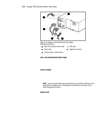
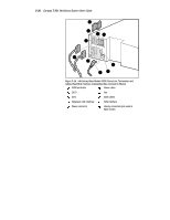
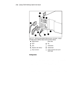
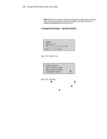
3-31 Compaq TL881 Minilibrary System Users Guide 1 10 23 9 4 7 8 6 5 SHR-1247 Figure 3-17. MiniLibrary Base Module SCSI Connectors, Terminator, Jumpers and Cables (SCSI-2 Interface, Daisy-chained Connection Shown) 1 SCSI terminator 6 Power cable 2 DLT0 7 Fan 3 DLT1 8 SCSI jumpers 4 Expansion Unit interface 9 SCSI interface 5 Power connector - Library connectors (not used in Slave mode) Configuration Individual MiniLibrary Base Modules in all newly assembled systems must be configured as described in the next section. In addition, the MiniLibrary System is designed with several configuration options, each offering multiple settings to support a variety of applications and platforms. The setting of each option is stored in non-volatile memory in the module. For most applications, you will not need to change the factory default settings. To change settings, you need to use the control panel on the Expansion Unit. For an overview of how the control panel works, and a description of the functions of the buttons, indicators and display, refer to sections entitled Entering the Menu Mode, Exiting the Menu Mode, and Navigating Through the Menu Structure in Chapter 2, Operation.
-
 1
1 -
2
-
3
-
4
-
5
-
6
-
7
-
8
-
9
-
10
-
11
-
12
-
13
-
14
-
15
-
16
-
17
-
18
-
19
-
20
-
21
-
22
-
23
-
24
-
25
-
26
-
27
-
28
-
29
-
30
-
31
-
32
-
33
-
34
-
35
-
36
-
37
-
38
-
39
-
40
-
41
-
42
-
43
-
44
-
45
-
46
-
47
-
48
-
49
-
50
-
51
-
52
-
53
-
54
-
55
-
56
-
57
-
58
-
59
-
60
-
61
-
62
-
63
-
64
-
65
-
66
-
67
-
68
-
69
-
70
-
71
-
72
-
73
-
74
-
75
-
76
-
77
-
78
-
79
-
80
-
81
-
82
-
83
-
84
-
85
-
86
-
87
-
88
-
89
-
90
-
91
-
92
-
93
-
94
-
 95
95 -
 96
96 -
 97
97 -
 98
98 -
 99
99 -
 100
100 -
 101
101 -
 102
102 -
 103
103 -
 104
104 -
 105
105 -
106
-
107
-
108
-
109
-
110
-
111
-
112
-
113
-
114
-
115
-
116
-
117
-
118
-
119
-
120
-
121
-
122
-
123
-
124
-
125
-
126
-
127
-
128
-
129
-
130
-
131
-
132
-
133
-
134
-
135
-
136
-
137
-
138
-
139
-
140
-
141
-
142
-
143
-
144
-
145
-
146
-
147
-
148
-
149
-
150
-
151
-
152
-
153
-
154
-
155
-
156
-
157
-
158
-
159
-
160
-
161
-
162
-
163
-
164
-
165
-
166
-
167
-
168
-
169
-
170
-
171
-
172
-
173
-
174
-
175
-
176
-
177
-
178
-
179
-
180
-
181
-
182
-
183
-
184
-
185
-
186
-
187
-
188
-
189
-
190
-
191
-
192
-
193
-
194
-
195
-
196
-
197
-
198
-
199
-
200
 |
 |
