HP SW TL881 DLT Mini-Lib/1 Compaq TL881 MiniLibrary System Users Guide (May 19 - Page 88
Rackmounting in a StorageWorks SW500, SW600, or SW800 Metric Cabinet, Interfaces and Cabling
 |
View all HP SW TL881 DLT Mini-Lib/1 manuals
Add to My Manuals
Save this manual to your list of manuals |
Page 88 highlights
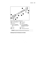
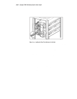
Installation 3-19 5. In front of the rack, lift the module to its installed height. Engage the inner slides mounted on the module with the intermediate slides protruding from the rack, and slide the module toward the rack until the inner slide lock engages the intermediate slide. This leaves the entire module protruding from the rack, locked in position, supported by slides. 6. Press inward (toward the module) on each of the inner slide locks to permit the intermediate slides to move toward the rack. 7. Slide the module in and out several times, ensuring that the inner and outer slide locks engage, and that the module does not bind against the slides. 8. If binding occurs, loosen the four screws that secure the slides to the front rails and the four screws that secure the slides to the rear rails. 9. If necessary, repeat steps 8 and 9 until the module does not bind against the slides. 10. If the rails on your rack are not threaded, install a clip nut on each front rail at the height of the captive screws on the front panel of the MiniLibrary Base Module. If the rails on your rack are threaded, skip this step. 11. Slide the MiniLibrary Base Module into the rack, and tighten the captive screws. 12. Once you have securely installed the MiniLibrary into the standard rack, proceed to the section entitled Interfaces and Cabling. Rackmounting in a StorageWorks (SW500, SW600, or SW800) Metric Cabinet These procedures assume that you have already separated the slide racks and have attached the mounting brackets to the slides as described in the beginning of this chapter. You are now ready to install the metric conversion brackets supplied with the MiniLibrary Base Module. These adapter brackets are designed to mount 4U high (IU=1.75") RETMA modules into a metric rack. The brackets maintain the 4U high unit-to-unit spacing on a metric rack which enables the Pass-Thru system to work properly.
-
 1
1 -
2
-
3
-
4
-
5
-
6
-
7
-
8
-
9
-
10
-
11
-
12
-
13
-
14
-
15
-
16
-
17
-
18
-
19
-
20
-
21
-
22
-
23
-
24
-
25
-
26
-
27
-
28
-
29
-
30
-
31
-
32
-
33
-
34
-
35
-
36
-
37
-
38
-
39
-
40
-
41
-
42
-
43
-
44
-
45
-
46
-
47
-
48
-
49
-
50
-
51
-
52
-
53
-
54
-
55
-
56
-
57
-
58
-
59
-
60
-
61
-
62
-
63
-
64
-
65
-
66
-
67
-
68
-
69
-
70
-
71
-
72
-
73
-
74
-
75
-
76
-
77
-
78
-
79
-
80
-
81
-
82
-
 83
83 -
 84
84 -
 85
85 -
 86
86 -
 87
87 -
 88
88 -
 89
89 -
 90
90 -
 91
91 -
 92
92 -
 93
93 -
94
-
95
-
96
-
97
-
98
-
99
-
100
-
101
-
102
-
103
-
104
-
105
-
106
-
107
-
108
-
109
-
110
-
111
-
112
-
113
-
114
-
115
-
116
-
117
-
118
-
119
-
120
-
121
-
122
-
123
-
124
-
125
-
126
-
127
-
128
-
129
-
130
-
131
-
132
-
133
-
134
-
135
-
136
-
137
-
138
-
139
-
140
-
141
-
142
-
143
-
144
-
145
-
146
-
147
-
148
-
149
-
150
-
151
-
152
-
153
-
154
-
155
-
156
-
157
-
158
-
159
-
160
-
161
-
162
-
163
-
164
-
165
-
166
-
167
-
168
-
169
-
170
-
171
-
172
-
173
-
174
-
175
-
176
-
177
-
178
-
179
-
180
-
181
-
182
-
183
-
184
-
185
-
186
-
187
-
188
-
189
-
190
-
191
-
192
-
193
-
194
-
195
-
196
-
197
-
198
-
199
-
200
 |
 |
