HP SW TL881 DLT Mini-Lib/1 Compaq TL881 MiniLibrary System Users Guide (May 19 - Page 180
Removing and Replacing the Drive Caddy Assembly, Removing
 |
View all HP SW TL881 DLT Mini-Lib/1 manuals
Add to My Manuals
Save this manual to your list of manuals |
Page 180 highlights
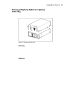
Adding a Second Tape Drive D-5 Figure D-3. Removing the Cover Plate SHR-120366 Removing and Replacing the Drive Caddy Assembly The drive caddy assembly is an enclosure that holds one or two DLT drives and the interconnecting cables. The assembly includes the SCSI interface connectors and cables for the base module, the power cables for the drives, and communication cables from the drives to the controller PWB. Removing Do these steps to remove the drive caddy assembly from the base module. 1. Remove the cover plate as described in Removing and Replacing the Cover Plate. 2. Disconnect the SCSI cable connectors (1) ( Figure D-4) from the controller SCSI extension cable.
-
 1
1 -
2
-
3
-
4
-
5
-
6
-
7
-
8
-
9
-
10
-
11
-
12
-
13
-
14
-
15
-
16
-
17
-
18
-
19
-
20
-
21
-
22
-
23
-
24
-
25
-
26
-
27
-
28
-
29
-
30
-
31
-
32
-
33
-
34
-
35
-
36
-
37
-
38
-
39
-
40
-
41
-
42
-
43
-
44
-
45
-
46
-
47
-
48
-
49
-
50
-
51
-
52
-
53
-
54
-
55
-
56
-
57
-
58
-
59
-
60
-
61
-
62
-
63
-
64
-
65
-
66
-
67
-
68
-
69
-
70
-
71
-
72
-
73
-
74
-
75
-
76
-
77
-
78
-
79
-
80
-
81
-
82
-
83
-
84
-
85
-
86
-
87
-
88
-
89
-
90
-
91
-
92
-
93
-
94
-
95
-
96
-
97
-
98
-
99
-
100
-
101
-
102
-
103
-
104
-
105
-
106
-
107
-
108
-
109
-
110
-
111
-
112
-
113
-
114
-
115
-
116
-
117
-
118
-
119
-
120
-
121
-
122
-
123
-
124
-
125
-
126
-
127
-
128
-
129
-
130
-
131
-
132
-
133
-
134
-
135
-
136
-
137
-
138
-
139
-
140
-
141
-
142
-
143
-
144
-
145
-
146
-
147
-
148
-
149
-
150
-
151
-
152
-
153
-
154
-
155
-
156
-
157
-
158
-
159
-
160
-
161
-
162
-
163
-
164
-
165
-
166
-
167
-
168
-
169
-
170
-
171
-
172
-
173
-
174
-
 175
175 -
 176
176 -
 177
177 -
 178
178 -
 179
179 -
 180
180 -
 181
181 -
 182
182 -
 183
183 -
 184
184 -
 185
185 -
186
-
187
-
188
-
189
-
190
-
191
-
192
-
193
-
194
-
195
-
196
-
197
-
198
-
199
-
200
 |
 |

Adding a Second Tape Drive
D-5
SHR-1203
66
Figure D-3.
Removing the Cover Plate
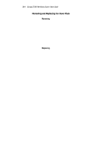
Removing and Replacing the Drive Caddy Assembly
The drive caddy assembly is an enclosure that holds one or two DLT drives
and the interconnecting cables. The assembly includes the SCSI interface
connectors and cables for the base module, the power cables for the drives,
and communication cables from the drives to the controller PWB.
Removing
Do these steps to remove the drive caddy assembly from the base module.
1.
Remove the cover plate as described in
Removing and Replacing the
Cover Plate
.
2.
Disconnect the SCSI cable connectors (1) ( Figure D-4) from the
controller SCSI extension cable.