HP SW TL881 DLT Mini-Lib/1 Compaq TL881 MiniLibrary System Users Guide (May 19 - Page 90
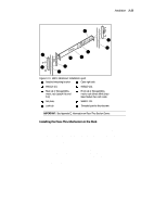
Metric Rackmount Procedure, If installing the first module, select a, mounting location
 |
View all HP SW TL881 DLT Mini-Lib/1 manuals
Add to My Manuals
Save this manual to your list of manuals |
Page 90 highlights
Installation 3-21 4 pieces 968313-101 b. If the module you are installing is going to be located third or fourth from the top (unit 3 and 4), the parts which you will need to install this module are: 2 pieces 968319-101 4 pieces 968320-101 c. If the module you are installing is going to be located fifth or sixth from the top (unit 5 and 6), the parts which you will need to install this module are: 2 pieces 968608-101 4 pieces 968609-101 d. Sort out the appropriate adapters for your application. The part number is stamped in the middle of the part for identification. 3. Next to each mounting hole in the bracket, numbers are stamped which correspond to the module number. If you are installing the first module for example, mount the flat head screws (P/N 213164-108) through the holes marked #1. Metric Rackmount Procedure: 1. Refer to Figure 3-13, Metric Rackmount Installation Layout. Mount the appropriate metric conversion bracket to both ends of the slide using the 10-32 nuts provided in the slide kit. Do this for both the left and right slide assembly. For modules 1 and 2, use P/N 968313-101. For modules 3 and 4, use P/N 968320-101; for modules 5 and 6, use P/N 968609-101 Make sure that these brackets are oriented so that the numbers are right side up in all corners. 2. Mounting the bracket/slide assembly to the StorageWorks cabinet: If installing the first module, select a mounting location: a. Mount each slide/bracket assembly to the rack by aligning the two mounting holes marked #1 to holes on the rack. Start by mounting the slide/bracket assembly to the rear of the StorageWorks first. Hold the bracket/slide assembly in place with one hand, fasten a mounting screw to the holes marked #1. b. To mount the front bracket, place bracket (P/N 968312-101) in front of the rack with the holes marked #1 aligned to the holes on the rack.
-
 1
1 -
2
-
3
-
4
-
5
-
6
-
7
-
8
-
9
-
10
-
11
-
12
-
13
-
14
-
15
-
16
-
17
-
18
-
19
-
20
-
21
-
22
-
23
-
24
-
25
-
26
-
27
-
28
-
29
-
30
-
31
-
32
-
33
-
34
-
35
-
36
-
37
-
38
-
39
-
40
-
41
-
42
-
43
-
44
-
45
-
46
-
47
-
48
-
49
-
50
-
51
-
52
-
53
-
54
-
55
-
56
-
57
-
58
-
59
-
60
-
61
-
62
-
63
-
64
-
65
-
66
-
67
-
68
-
69
-
70
-
71
-
72
-
73
-
74
-
75
-
76
-
77
-
78
-
79
-
80
-
81
-
82
-
83
-
84
-
 85
85 -
 86
86 -
 87
87 -
 88
88 -
 89
89 -
 90
90 -
 91
91 -
 92
92 -
 93
93 -
 94
94 -
 95
95 -
96
-
97
-
98
-
99
-
100
-
101
-
102
-
103
-
104
-
105
-
106
-
107
-
108
-
109
-
110
-
111
-
112
-
113
-
114
-
115
-
116
-
117
-
118
-
119
-
120
-
121
-
122
-
123
-
124
-
125
-
126
-
127
-
128
-
129
-
130
-
131
-
132
-
133
-
134
-
135
-
136
-
137
-
138
-
139
-
140
-
141
-
142
-
143
-
144
-
145
-
146
-
147
-
148
-
149
-
150
-
151
-
152
-
153
-
154
-
155
-
156
-
157
-
158
-
159
-
160
-
161
-
162
-
163
-
164
-
165
-
166
-
167
-
168
-
169
-
170
-
171
-
172
-
173
-
174
-
175
-
176
-
177
-
178
-
179
-
180
-
181
-
182
-
183
-
184
-
185
-
186
-
187
-
188
-
189
-
190
-
191
-
192
-
193
-
194
-
195
-
196
-
197
-
198
-
199
-
200
 |
 |
