HP SW TL881 DLT Mini-Lib/1 Compaq TL881 MiniLibrary System Users Guide (May 19 - Page 21
Features, Control Panel, Display, Magazine Security Lock, Power Supply
 |
View all HP SW TL881 DLT Mini-Lib/1 manuals
Add to My Manuals
Save this manual to your list of manuals |
Page 21 highlights
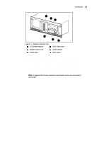
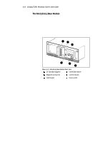
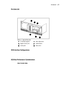
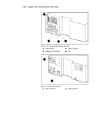
Introduction 1-7 System firmware integrates all of the robotics of these system modules with that of the Pass-Thru Mechanism into a single high-performance library robotics system. Features There are a number of important external features to note about the Expansion Unit, the MiniLibrary Base Module and the Data Unit. See Figures 1-1 through 1-7 to locate the features described here. Control Panel The control panels for all modules are the same, except for the number of LED indicators. The control panel features a 4-line by 20-character backlit LCD display, three or four LED indicators, and four buttons. The buttons enable the operator to navigate through the menu structure to select and display operating modes, device status, diagnostic and maintenance functions, device history and error statistics, and system configuration. The functions of the control panel are described in detail in Chapter 2, Operation. Display The backlit 4-line by 20-character control panel display provides a highly intelligible presentation of drive and loader status, menu choices and error messages. The scrolling feature greatly expands the amount of information available to the operator. In the Expansion Unit, status information is available for the entire system. The MiniLibrary Base Modules display other information as needed for localizing malfunctions. Magazine Security Lock The Magazine Security Lock is a key-operated switch on the front panel of each module. It can be used to prevent inadvertent removal of the cartridge magazine. Power Supply The AC Power switch is located on the front panel of the module. The autoranging power supply will adjust automatically to either of two operating voltage ranges. The ranges are 100-120 VAC and 200-240 VAC. The power supply is capable of operating at 50 or 60 Hz without any adjustment or modification. AC power is supplied to the power supply by a single IECcompatible socket that can be connected to any properly grounded outlet.
-
 1
1 -
2
-
3
-
4
-
5
-
6
-
7
-
8
-
9
-
10
-
11
-
12
-
13
-
14
-
15
-
 16
16 -
 17
17 -
 18
18 -
 19
19 -
 20
20 -
 21
21 -
 22
22 -
 23
23 -
 24
24 -
 25
25 -
 26
26 -
27
-
28
-
29
-
30
-
31
-
32
-
33
-
34
-
35
-
36
-
37
-
38
-
39
-
40
-
41
-
42
-
43
-
44
-
45
-
46
-
47
-
48
-
49
-
50
-
51
-
52
-
53
-
54
-
55
-
56
-
57
-
58
-
59
-
60
-
61
-
62
-
63
-
64
-
65
-
66
-
67
-
68
-
69
-
70
-
71
-
72
-
73
-
74
-
75
-
76
-
77
-
78
-
79
-
80
-
81
-
82
-
83
-
84
-
85
-
86
-
87
-
88
-
89
-
90
-
91
-
92
-
93
-
94
-
95
-
96
-
97
-
98
-
99
-
100
-
101
-
102
-
103
-
104
-
105
-
106
-
107
-
108
-
109
-
110
-
111
-
112
-
113
-
114
-
115
-
116
-
117
-
118
-
119
-
120
-
121
-
122
-
123
-
124
-
125
-
126
-
127
-
128
-
129
-
130
-
131
-
132
-
133
-
134
-
135
-
136
-
137
-
138
-
139
-
140
-
141
-
142
-
143
-
144
-
145
-
146
-
147
-
148
-
149
-
150
-
151
-
152
-
153
-
154
-
155
-
156
-
157
-
158
-
159
-
160
-
161
-
162
-
163
-
164
-
165
-
166
-
167
-
168
-
169
-
170
-
171
-
172
-
173
-
174
-
175
-
176
-
177
-
178
-
179
-
180
-
181
-
182
-
183
-
184
-
185
-
186
-
187
-
188
-
189
-
190
-
191
-
192
-
193
-
194
-
195
-
196
-
197
-
198
-
199
-
200
 |
 |
