HP SW TL881 DLT Mini-Lib/1 Compaq TL881 MiniLibrary System Users Guide (May 19 - Page 181
drive caddy assembly., Remove two M4 x 8mm flat-head screws 4 along the upper edge of
 |
View all HP SW TL881 DLT Mini-Lib/1 manuals
Add to My Manuals
Save this manual to your list of manuals |
Page 181 highlights
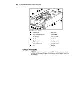
D-6 Compaq TL881 Minilibrary System Users Guide 5 27 1 7 5 3 6 4 4 Figure D-4. Drive Caddy SHR-1204 3. Disconnect the drive power "Y" cable (2) from the power supply connector. 4. Disconnect the drive 1 RS-422 cable (3) at the controller PWB end. 5. Remove two M4 x 8mm flat-head screws (4) along the upper edge of the drive caddy assembly. 6. Remove two M4 extension screws (5) at the top of the drive caddy assembly. CAUTION: If you're not careful, you might break the door levers when you lift the drive caddy assembly out of the base module in the next step. To prevent this, steady the caddy so it cannot rock forward as it clears the platform when you're lifting it up, and do not allow the door levers to touch the strut across the top of the base module. 7. Grasp the handle on top and lift the drive caddy assembly out of the base module carefully; be careful the door levers don't bump against the chassis crossbrace.
-
 1
1 -
2
-
3
-
4
-
5
-
6
-
7
-
8
-
9
-
10
-
11
-
12
-
13
-
14
-
15
-
16
-
17
-
18
-
19
-
20
-
21
-
22
-
23
-
24
-
25
-
26
-
27
-
28
-
29
-
30
-
31
-
32
-
33
-
34
-
35
-
36
-
37
-
38
-
39
-
40
-
41
-
42
-
43
-
44
-
45
-
46
-
47
-
48
-
49
-
50
-
51
-
52
-
53
-
54
-
55
-
56
-
57
-
58
-
59
-
60
-
61
-
62
-
63
-
64
-
65
-
66
-
67
-
68
-
69
-
70
-
71
-
72
-
73
-
74
-
75
-
76
-
77
-
78
-
79
-
80
-
81
-
82
-
83
-
84
-
85
-
86
-
87
-
88
-
89
-
90
-
91
-
92
-
93
-
94
-
95
-
96
-
97
-
98
-
99
-
100
-
101
-
102
-
103
-
104
-
105
-
106
-
107
-
108
-
109
-
110
-
111
-
112
-
113
-
114
-
115
-
116
-
117
-
118
-
119
-
120
-
121
-
122
-
123
-
124
-
125
-
126
-
127
-
128
-
129
-
130
-
131
-
132
-
133
-
134
-
135
-
136
-
137
-
138
-
139
-
140
-
141
-
142
-
143
-
144
-
145
-
146
-
147
-
148
-
149
-
150
-
151
-
152
-
153
-
154
-
155
-
156
-
157
-
158
-
159
-
160
-
161
-
162
-
163
-
164
-
165
-
166
-
167
-
168
-
169
-
170
-
171
-
172
-
173
-
174
-
175
-
 176
176 -
 177
177 -
 178
178 -
 179
179 -
 180
180 -
 181
181 -
 182
182 -
 183
183 -
 184
184 -
 185
185 -
 186
186 -
187
-
188
-
189
-
190
-
191
-
192
-
193
-
194
-
195
-
196
-
197
-
198
-
199
-
200
 |
 |
