HP rp8420 HP 9000 rp8420 Server - User Service Guide, Fifth Edition - Page 120
Replacing a Cell Board, Extraction Lever
 |
View all HP rp8420 manuals
Add to My Manuals
Save this manual to your list of manuals |
Page 120 highlights
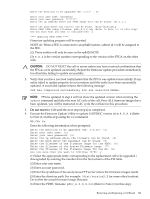
Replacing a Cell Board NOTE: The cell board weighs 27.8 lb. Support both side edges while replacing the cell board into the chassis. 1. Move the slide to the unlocked position and fully open each latch on the cell board. 2. Insert the cell board into the guide rails. Slide into the chassis until the cell board levers contact the cell board guide rails. See Figure 6-19 for details. 3. Using equal pressure, simultaneously press both extraction levers to seat the cell board in the chassis. 4. Move each slide to the locked position and release the lever. Refer to Figure 6-20. Figure 6-20 Extraction Lever Ensure that both levers are in the locked position. If both levers are not locked, the cell board will not power up. 5. Enter de from the Command Menu to verify that the extraction levers are locked and the cell board is in the proper operational status. See Figure 6-21 (page 121). 6. Enter h to select the Cell Board Controller (PDHC) and then enter the cell number. 120 Removal and Replacement
-
 1
1 -
2
-
3
-
4
-
5
-
6
-
7
-
8
-
9
-
10
-
11
-
12
-
13
-
14
-
15
-
16
-
17
-
18
-
19
-
20
-
21
-
22
-
23
-
24
-
25
-
26
-
27
-
28
-
29
-
30
-
31
-
32
-
33
-
34
-
35
-
36
-
37
-
38
-
39
-
40
-
41
-
42
-
43
-
44
-
45
-
46
-
47
-
48
-
49
-
50
-
51
-
52
-
53
-
54
-
55
-
56
-
57
-
58
-
59
-
60
-
61
-
62
-
63
-
64
-
65
-
66
-
67
-
68
-
69
-
70
-
71
-
72
-
73
-
74
-
75
-
76
-
77
-
78
-
79
-
80
-
81
-
82
-
83
-
84
-
85
-
86
-
87
-
88
-
89
-
90
-
91
-
92
-
93
-
94
-
95
-
96
-
97
-
98
-
99
-
100
-
101
-
102
-
103
-
104
-
105
-
106
-
107
-
108
-
109
-
110
-
111
-
112
-
113
-
114
-
 115
115 -
 116
116 -
 117
117 -
 118
118 -
 119
119 -
 120
120 -
 121
121 -
 122
122 -
 123
123 -
 124
124 -
 125
125 -
126
-
127
-
128
-
129
-
130
-
131
-
132
-
133
-
134
-
135
-
136
-
137
-
138
-
139
-
140
-
141
-
142
-
143
-
144
-
145
-
146
-
147
-
148
-
149
-
150
-
151
-
152
-
153
-
154
-
155
-
156
-
157
-
158
-
159
-
160
-
161
-
162
-
163
-
164
-
165
-
166
-
167
-
168
-
169
-
170
-
171
-
172
-
173
-
174
-
175
-
176
-
177
-
178
-
179
-
180
-
181
-
182
-
183
-
184
-
185
-
186
-
187
-
188
-
189
-
190
-
191
-
192
-
193
-
194
-
195
-
196
-
197
-
198
-
199
-
200
-
201
-
202
-
203
-
204
-
205
-
206
-
207
-
208
-
209
-
210
-
211
-
212
-
213
-
214
-
215
 |
 |
