HP rp8420 HP 9000 rp8420 Server - User Service Guide, Fifth Edition - Page 61
Voltage Check (Additional Procedure)
 |
View all HP rp8420 manuals
Add to My Manuals
Save this manual to your list of manuals |
Page 61 highlights
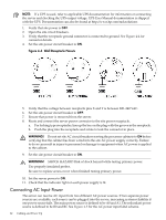
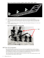
Figure 4-3 Safety Ground Reference Check-Dual Power Source 1. Measure the voltage between A0 and A1. Take the AC voltage down to the lowest scale on the volt meter. One probe is inserted into the ground pin for A0. The other probe is inserted into the ground pin for A1. Verify that the measurement is between 0-5 VAC. If the measurement is 5 V or greater, escalate the situation. Do not attempt to plug the power cords into the server cabinet. 2. Measure the voltage between B0 and B1. Take the AC voltage down to the lowest scale on the volt meter. One probe is inserted into the ground pin for B0. The other probe is inserted into the ground pin for B1. Verify that the measurement is between 0-5 VAC. If the measurement is 5 V or greater, escalate the situation. Do not attempt to plug the power cords into the server cabinet. 3. Measure the voltage between A0 and B0. Take the AC voltage down to the lowest scale on the volt meter. One probe is inserted into the ground pin for A0. The other probe is inserted into the ground pin for B0. Verify that the measurement is between 0-5 VAC. If the measurement is 5 V or greater, escalate the situation. Do not attempt to plug the power cords into the server cabinet. 4. Measure the voltage between A1 and B1. Take the AC voltage down to the lowest scale on the volt meter. One probe is inserted into the ground pin for A1. The other probe is inserted into the ground pin for B1. Verify that the measurement is between 0-5 VAC. If the measurement is 5 V or greater, escalate the situation. Do not attempt to plug the power cords into the server cabinet. Voltage Check (Additional Procedure) The voltage check ensures that all phases (and neutral, for international systems) are connected correctly to the cabinet and that the AC input voltage is within limits. Perform this procedure if the previous voltage check procedure did not yield the expected results as previously outlined. Voltage Check (Additional Procedure) 61
-
 1
1 -
2
-
3
-
4
-
5
-
6
-
7
-
8
-
9
-
10
-
11
-
12
-
13
-
14
-
15
-
16
-
17
-
18
-
19
-
20
-
21
-
22
-
23
-
24
-
25
-
26
-
27
-
28
-
29
-
30
-
31
-
32
-
33
-
34
-
35
-
36
-
37
-
38
-
39
-
40
-
41
-
42
-
43
-
44
-
45
-
46
-
47
-
48
-
49
-
50
-
51
-
52
-
53
-
54
-
55
-
 56
56 -
 57
57 -
 58
58 -
 59
59 -
 60
60 -
 61
61 -
 62
62 -
 63
63 -
 64
64 -
 65
65 -
 66
66 -
67
-
68
-
69
-
70
-
71
-
72
-
73
-
74
-
75
-
76
-
77
-
78
-
79
-
80
-
81
-
82
-
83
-
84
-
85
-
86
-
87
-
88
-
89
-
90
-
91
-
92
-
93
-
94
-
95
-
96
-
97
-
98
-
99
-
100
-
101
-
102
-
103
-
104
-
105
-
106
-
107
-
108
-
109
-
110
-
111
-
112
-
113
-
114
-
115
-
116
-
117
-
118
-
119
-
120
-
121
-
122
-
123
-
124
-
125
-
126
-
127
-
128
-
129
-
130
-
131
-
132
-
133
-
134
-
135
-
136
-
137
-
138
-
139
-
140
-
141
-
142
-
143
-
144
-
145
-
146
-
147
-
148
-
149
-
150
-
151
-
152
-
153
-
154
-
155
-
156
-
157
-
158
-
159
-
160
-
161
-
162
-
163
-
164
-
165
-
166
-
167
-
168
-
169
-
170
-
171
-
172
-
173
-
174
-
175
-
176
-
177
-
178
-
179
-
180
-
181
-
182
-
183
-
184
-
185
-
186
-
187
-
188
-
189
-
190
-
191
-
192
-
193
-
194
-
195
-
196
-
197
-
198
-
199
-
200
-
201
-
202
-
203
-
204
-
205
-
206
-
207
-
208
-
209
-
210
-
211
-
212
-
213
-
214
-
215
 |
 |
