HP rp8420 HP 9000 rp8420 Server - User Service Guide, Fifth Edition - Page 42
Using the RonI Model 17000 SP 400 Lifting Device, HP J1528A Rack Integration Kit Installation Guide - service manual
 |
View all HP rp8420 manuals
Add to My Manuals
Save this manual to your list of manuals |
Page 42 highlights
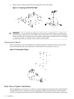
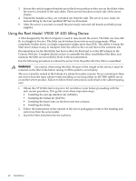
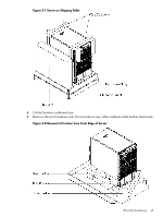
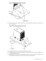
3. Ensure the vertical support brackets are in the down position so they rest on the slides when the server is lowered to the rack slides. There are two brackets on each side of the server chassis. 4. Unfold the handles so they are extended out from the unit. The server is now ready for manual lifting by the four qualified HP Service Personnel. 5. After the server is secured, re-install the previously removed cell boards and bulk power supplies. Using the RonI Model 17000 SP 400 Lifting Device A lifter designed by the RonI company is used to rack-mount the server. The lifter can raise 400 lb. to a height of five feet. The lifter can be broken down into several components. When completely broken down, no single component weighs more than 25 lb. The ability to break the lifter down makes it easy to transport from the office to the car and then to the customer site. Documentation for the RonI lifter has been written by RonI and is on the HP intranet at the Cybrary Web site. Complete details on how to assemble the lifter, troubleshoot the lifter, and maintain the lifter are provided by RonI in the documentation. Use the following procedure to unload the server from the pallet after the lifter is assembled. WARNING! Use caution when using the lifter. Because of the weight of the server, it must be centered on the lifter forks before raising it off the pallet to avoid injury. The server must be racked in the bottom of a cabinet for safety reasons. Never extend more than one server from the same cabinet while installing or servicing either an HP 9000 rp8420 server or another server product. Failure to follow these instructions could result in the cabinet tipping over. 1. Obtain the HP J1528A Rack Integration Kit Installation Guide before proceeding with the rack-mount procedure. This guide covers these important steps: • Installing the anti-tip stabilizer kit (A5540A) • Installing the ballast kit (J1479A) • Installing the barrel nuts on the front and rear columns • Installing the slides 2. Follow the instructions on the outside of the server packaging to remove the banding and carton top from the server pallet. 3. Insert the lifter forks between the cushions. 42 Installation
-
 1
1 -
2
-
3
-
4
-
5
-
6
-
7
-
8
-
9
-
10
-
11
-
12
-
13
-
14
-
15
-
16
-
17
-
18
-
19
-
20
-
21
-
22
-
23
-
24
-
25
-
26
-
27
-
28
-
29
-
30
-
31
-
32
-
33
-
34
-
35
-
36
-
 37
37 -
 38
38 -
 39
39 -
 40
40 -
 41
41 -
 42
42 -
 43
43 -
 44
44 -
 45
45 -
 46
46 -
 47
47 -
48
-
49
-
50
-
51
-
52
-
53
-
54
-
55
-
56
-
57
-
58
-
59
-
60
-
61
-
62
-
63
-
64
-
65
-
66
-
67
-
68
-
69
-
70
-
71
-
72
-
73
-
74
-
75
-
76
-
77
-
78
-
79
-
80
-
81
-
82
-
83
-
84
-
85
-
86
-
87
-
88
-
89
-
90
-
91
-
92
-
93
-
94
-
95
-
96
-
97
-
98
-
99
-
100
-
101
-
102
-
103
-
104
-
105
-
106
-
107
-
108
-
109
-
110
-
111
-
112
-
113
-
114
-
115
-
116
-
117
-
118
-
119
-
120
-
121
-
122
-
123
-
124
-
125
-
126
-
127
-
128
-
129
-
130
-
131
-
132
-
133
-
134
-
135
-
136
-
137
-
138
-
139
-
140
-
141
-
142
-
143
-
144
-
145
-
146
-
147
-
148
-
149
-
150
-
151
-
152
-
153
-
154
-
155
-
156
-
157
-
158
-
159
-
160
-
161
-
162
-
163
-
164
-
165
-
166
-
167
-
168
-
169
-
170
-
171
-
172
-
173
-
174
-
175
-
176
-
177
-
178
-
179
-
180
-
181
-
182
-
183
-
184
-
185
-
186
-
187
-
188
-
189
-
190
-
191
-
192
-
193
-
194
-
195
-
196
-
197
-
198
-
199
-
200
-
201
-
202
-
203
-
204
-
205
-
206
-
207
-
208
-
209
-
210
-
211
-
212
-
213
-
214
-
215
 |
 |
