HP rp8420 HP 9000 rp8420 Server - User Service Guide, Fifth Edition - Page 44
Wheel Kit Installation, Installing the Server Wheel Kit
 |
View all HP rp8420 manuals
Add to My Manuals
Save this manual to your list of manuals |
Page 44 highlights
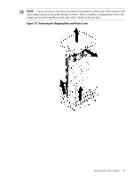
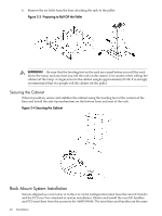
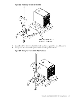
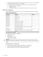
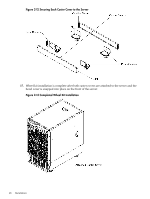
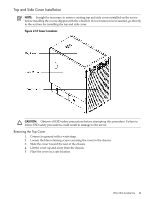
6. Carefully roll the lifter and server away from the pallet. Do not raise the server any higher than necessary when moving it over to the rack. 7. Follow the HP J1528A Rack Integration Kit Installation Guide to complete these steps: • Mounting the server to the slides • Installing the CMA • Installing the interlock device assembly (if two servers are in the same cabinet) Wheel Kit Installation Compare the packing list with the contents of the wheel kit before beginning the installation. Table 2-1 Wheel Kit Packing List Part Number A9904-04002 A9904-04007 A9904-04008 A9904-04009 A6093-04082 A6093-04083 A6093-04084 A6093-04085 0515-2478 A6093-44013 Not Applicable Description Quantity Caster Cover 2 Right Side Cover 1 Left Side Cover 1 Top Cover 1 Right Front Caster Assembly 1 Right Rear Caster Assembly 1 Left Front Caster Assembly 1 Left Rear Caster Assembly 1 M4 x 0.7 8mm T15 Steel Zinc Machine Screw (used to attach 8 each caster to the chassis) Plywood Unloading Ramp 1 Phillips Head Wood Screw (used to attach the ramp to the 2 pallet) Tools Required for Installation The following list provides the installer with the recommended tools to perform the wheel kit installation. • Diagonal side cutters • Safety glasses • Torx driver with T-15 bit • Phillips head screwdriver WARNING! Wear protective glasses while cutting the plastic bands around the shipping container. These bands are under tension. When cut, they can spring back and cause serious eye injury. Installing the Server Wheel Kit 1. Cut and remove the polystrap bands securing the server to the pallet. 2. Lift the carton top from the cardboard tray resting on the pallet. 3. Remove the bezel kit carton and top cushion from the pallet. 44 Installation
-
 1
1 -
2
-
3
-
4
-
5
-
6
-
7
-
8
-
9
-
10
-
11
-
12
-
13
-
14
-
15
-
16
-
17
-
18
-
19
-
20
-
21
-
22
-
23
-
24
-
25
-
26
-
27
-
28
-
29
-
30
-
31
-
32
-
33
-
34
-
35
-
36
-
37
-
38
-
 39
39 -
 40
40 -
 41
41 -
 42
42 -
 43
43 -
 44
44 -
 45
45 -
 46
46 -
 47
47 -
 48
48 -
 49
49 -
50
-
51
-
52
-
53
-
54
-
55
-
56
-
57
-
58
-
59
-
60
-
61
-
62
-
63
-
64
-
65
-
66
-
67
-
68
-
69
-
70
-
71
-
72
-
73
-
74
-
75
-
76
-
77
-
78
-
79
-
80
-
81
-
82
-
83
-
84
-
85
-
86
-
87
-
88
-
89
-
90
-
91
-
92
-
93
-
94
-
95
-
96
-
97
-
98
-
99
-
100
-
101
-
102
-
103
-
104
-
105
-
106
-
107
-
108
-
109
-
110
-
111
-
112
-
113
-
114
-
115
-
116
-
117
-
118
-
119
-
120
-
121
-
122
-
123
-
124
-
125
-
126
-
127
-
128
-
129
-
130
-
131
-
132
-
133
-
134
-
135
-
136
-
137
-
138
-
139
-
140
-
141
-
142
-
143
-
144
-
145
-
146
-
147
-
148
-
149
-
150
-
151
-
152
-
153
-
154
-
155
-
156
-
157
-
158
-
159
-
160
-
161
-
162
-
163
-
164
-
165
-
166
-
167
-
168
-
169
-
170
-
171
-
172
-
173
-
174
-
175
-
176
-
177
-
178
-
179
-
180
-
181
-
182
-
183
-
184
-
185
-
186
-
187
-
188
-
189
-
190
-
191
-
192
-
193
-
194
-
195
-
196
-
197
-
198
-
199
-
200
-
201
-
202
-
203
-
204
-
205
-
206
-
207
-
208
-
209
-
210
-
211
-
212
-
213
-
214
-
215
 |
 |
