HP rp8420 HP 9000 rp8420 Server - User Service Guide, Fifth Edition - Page 171
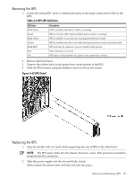
Removing the BPS, Table 6-6 BPS LED definitions, BPS Detail
 |
View all HP rp8420 manuals
Add to My Manuals
Save this manual to your list of manuals |
Page 171 highlights
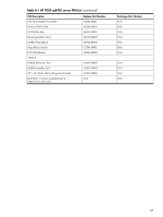
Removing the BPS 1. Isolate the failing BPS. Table 6-6 defines the states of the single multicolored LED on the BPS. Table 6-6 BPS LED definitions LED State Blink Green Green Blink Yellow Yellow Blink RED Red Off Description BPS in standby state and no faults or warnings BPS in run state (48V output enabled) and no faults or warnings BPS in standby or run state and warnings present but no faults BPS in standby state and recoverable faults present but no non-recoverable faults BPS state may be unknown, non-recoverable faults present This LED state is not used BPS fault or failure (unless AC power is not connected to server) 2. Remove the front bezel. 3. Depress the release latch on the upper-front center portion of the BPS. 4. Slide the BPS forward using the handle to remove it from the chassis. Figure 6-65 BPS Detail Replacing the BPS 1. Grip the handle with one hand while supporting the rear of BPS in the other hand. NOTE: The BPS easily slides into the chassis; however, a slow, firm pressure is needed to properly seat the connection. 2. Slide the power supply into the slot until fully seated. When seated, the release latch will click and lock into place. Removing and Replacing a BPS 171
-
 1
1 -
2
-
3
-
4
-
5
-
6
-
7
-
8
-
9
-
10
-
11
-
12
-
13
-
14
-
15
-
16
-
17
-
18
-
19
-
20
-
21
-
22
-
23
-
24
-
25
-
26
-
27
-
28
-
29
-
30
-
31
-
32
-
33
-
34
-
35
-
36
-
37
-
38
-
39
-
40
-
41
-
42
-
43
-
44
-
45
-
46
-
47
-
48
-
49
-
50
-
51
-
52
-
53
-
54
-
55
-
56
-
57
-
58
-
59
-
60
-
61
-
62
-
63
-
64
-
65
-
66
-
67
-
68
-
69
-
70
-
71
-
72
-
73
-
74
-
75
-
76
-
77
-
78
-
79
-
80
-
81
-
82
-
83
-
84
-
85
-
86
-
87
-
88
-
89
-
90
-
91
-
92
-
93
-
94
-
95
-
96
-
97
-
98
-
99
-
100
-
101
-
102
-
103
-
104
-
105
-
106
-
107
-
108
-
109
-
110
-
111
-
112
-
113
-
114
-
115
-
116
-
117
-
118
-
119
-
120
-
121
-
122
-
123
-
124
-
125
-
126
-
127
-
128
-
129
-
130
-
131
-
132
-
133
-
134
-
135
-
136
-
137
-
138
-
139
-
140
-
141
-
142
-
143
-
144
-
145
-
146
-
147
-
148
-
149
-
150
-
151
-
152
-
153
-
154
-
155
-
156
-
157
-
158
-
159
-
160
-
161
-
162
-
163
-
164
-
165
-
 166
166 -
 167
167 -
 168
168 -
 169
169 -
 170
170 -
 171
171 -
 172
172 -
 173
173 -
 174
174 -
 175
175 -
 176
176 -
177
-
178
-
179
-
180
-
181
-
182
-
183
-
184
-
185
-
186
-
187
-
188
-
189
-
190
-
191
-
192
-
193
-
194
-
195
-
196
-
197
-
198
-
199
-
200
-
201
-
202
-
203
-
204
-
205
-
206
-
207
-
208
-
209
-
210
-
211
-
212
-
213
-
214
-
215
 |
 |
