HP rp8420 HP 9000 rp8420 Server - User Service Guide, Fifth Edition - Page 147
Replacing a Turbo-Cooler Fan, Soldered Heatsink and Clip
 |
View all HP rp8420 manuals
Add to My Manuals
Save this manual to your list of manuals |
Page 147 highlights
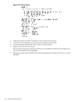
NOTE: There are two different heatsinks used in the turbo-cooler fan assemblies. The removal and replacement procedure is essentially the same between the two. The machined heatsink has thicker fins, and is one-piece. The other heatsink has fins that are thinner and soldered to a base-piece. The machined heatsink has a clip holding the power cable in place that cannot be removed. The soldered heatsink has a clip that must be removed in order to correctly route the cable. See Figure 6-38 and Figure 6-39. Figure 6-38 Soldered Heatsink and Clip Figure 6-39 Machined Heatsink and Clip 9. On the machined heatsink: note the fan power cable routing and unhook the fan power cable from the clip on the heatsink fin. Care should be used not to break the clip. On the soldered heatsink: note the power cable routing and remove the clip by sliding it up and off the heatsink fin. Remove the power cable from the clip and set the clip aside. Replacing a Turbo-Cooler Fan 1. Position the new fan with the power cable routed toward the clip. 2. Seat the replacement fan in the turbo-cooler by pressing down on the center of the fan. You should hear a snap when each of the two tabs engages. 3. Route the cable carefully through the fins of the heatsink without leaving excess slack inside which could impede the fan. On the soldered heatsink: after routing the cable, slide the clip onto the fin immediately next to where you routed the cable. 4. Secure the power cable in the clip. The fan will spin freely when seated properly with the fan power cable secured in the clip. 5. Plug the fan power cable into the cell board. 6. If so equipped, replace the CPU cover and tighten all the captive screws. Removing and Replacing a Processor Turbo-Cooler Fan 147
-
 1
1 -
2
-
3
-
4
-
5
-
6
-
7
-
8
-
9
-
10
-
11
-
12
-
13
-
14
-
15
-
16
-
17
-
18
-
19
-
20
-
21
-
22
-
23
-
24
-
25
-
26
-
27
-
28
-
29
-
30
-
31
-
32
-
33
-
34
-
35
-
36
-
37
-
38
-
39
-
40
-
41
-
42
-
43
-
44
-
45
-
46
-
47
-
48
-
49
-
50
-
51
-
52
-
53
-
54
-
55
-
56
-
57
-
58
-
59
-
60
-
61
-
62
-
63
-
64
-
65
-
66
-
67
-
68
-
69
-
70
-
71
-
72
-
73
-
74
-
75
-
76
-
77
-
78
-
79
-
80
-
81
-
82
-
83
-
84
-
85
-
86
-
87
-
88
-
89
-
90
-
91
-
92
-
93
-
94
-
95
-
96
-
97
-
98
-
99
-
100
-
101
-
102
-
103
-
104
-
105
-
106
-
107
-
108
-
109
-
110
-
111
-
112
-
113
-
114
-
115
-
116
-
117
-
118
-
119
-
120
-
121
-
122
-
123
-
124
-
125
-
126
-
127
-
128
-
129
-
130
-
131
-
132
-
133
-
134
-
135
-
136
-
137
-
138
-
139
-
140
-
141
-
 142
142 -
 143
143 -
 144
144 -
 145
145 -
 146
146 -
 147
147 -
 148
148 -
 149
149 -
 150
150 -
 151
151 -
 152
152 -
153
-
154
-
155
-
156
-
157
-
158
-
159
-
160
-
161
-
162
-
163
-
164
-
165
-
166
-
167
-
168
-
169
-
170
-
171
-
172
-
173
-
174
-
175
-
176
-
177
-
178
-
179
-
180
-
181
-
182
-
183
-
184
-
185
-
186
-
187
-
188
-
189
-
190
-
191
-
192
-
193
-
194
-
195
-
196
-
197
-
198
-
199
-
200
-
201
-
202
-
203
-
204
-
205
-
206
-
207
-
208
-
209
-
210
-
211
-
212
-
213
-
214
-
215
 |
 |
