HP rp8420 HP 9000 rp8420 Server - User Service Guide, Fifth Edition - Page 60
Safety Ground Verification Single Power Source, Table 4-1 Single-Phase Voltage Examples
 |
View all HP rp8420 manuals
Add to My Manuals
Save this manual to your list of manuals |
Page 60 highlights
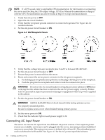
Table 4-1 Single-Phase Voltage Examples Japan North America L1-L2 210V 208V or 240V L1-GND 105V 120V L2-GND 105V 120V 1 In some European countries there might not be a polarization. Europe1 230V 230V 0V Safety Ground Verification (Single Power Source) This procedure measures the voltage level between A0 and A1. The voltage level between B0 and B1 will also be verified. All measurements will be taken between ground pins. See Figure 4-2 for ground reference points when performing these measurements. Figure 4-2 Safety Ground Reference Check-Single Power Source 1. Measure the voltage between A0 and A1. Take the AC voltage down to the lowest scale on the volt meter. One probe is inserted into the ground pin for A0. The other probe is inserted into the ground pin for A1. Verify that the measurement is between 0-5 VAC. If the measurement is 5 V or greater, escalate the situation. Do not attempt to plug the power cords into the server cabinet. 2. Measure the voltage between B0 and B1. Take the AC voltage down to the lowest scale on the volt meter. One probe will be inserted into the ground pin for B0. The other probe will be inserted into the ground pin for B1. Verify that the measurement is between 0-5 VAC. If the measurement is 5 V or greater, escalate the situation. Do not attempt to plug the power cords into the server cabinet. Safety Ground Verification (Dual Power Source) This procedure measures the voltage level between A0 and A1, between B0 and B1, between A0 and B0, and between A1 and B1. All measurements will be taken between ground pins. See Figure 4-3 for ground reference points when performing these measurements. 60 Cabling and Power Up
-
 1
1 -
2
-
3
-
4
-
5
-
6
-
7
-
8
-
9
-
10
-
11
-
12
-
13
-
14
-
15
-
16
-
17
-
18
-
19
-
20
-
21
-
22
-
23
-
24
-
25
-
26
-
27
-
28
-
29
-
30
-
31
-
32
-
33
-
34
-
35
-
36
-
37
-
38
-
39
-
40
-
41
-
42
-
43
-
44
-
45
-
46
-
47
-
48
-
49
-
50
-
51
-
52
-
53
-
54
-
 55
55 -
 56
56 -
 57
57 -
 58
58 -
 59
59 -
 60
60 -
 61
61 -
 62
62 -
 63
63 -
 64
64 -
 65
65 -
66
-
67
-
68
-
69
-
70
-
71
-
72
-
73
-
74
-
75
-
76
-
77
-
78
-
79
-
80
-
81
-
82
-
83
-
84
-
85
-
86
-
87
-
88
-
89
-
90
-
91
-
92
-
93
-
94
-
95
-
96
-
97
-
98
-
99
-
100
-
101
-
102
-
103
-
104
-
105
-
106
-
107
-
108
-
109
-
110
-
111
-
112
-
113
-
114
-
115
-
116
-
117
-
118
-
119
-
120
-
121
-
122
-
123
-
124
-
125
-
126
-
127
-
128
-
129
-
130
-
131
-
132
-
133
-
134
-
135
-
136
-
137
-
138
-
139
-
140
-
141
-
142
-
143
-
144
-
145
-
146
-
147
-
148
-
149
-
150
-
151
-
152
-
153
-
154
-
155
-
156
-
157
-
158
-
159
-
160
-
161
-
162
-
163
-
164
-
165
-
166
-
167
-
168
-
169
-
170
-
171
-
172
-
173
-
174
-
175
-
176
-
177
-
178
-
179
-
180
-
181
-
182
-
183
-
184
-
185
-
186
-
187
-
188
-
189
-
190
-
191
-
192
-
193
-
194
-
195
-
196
-
197
-
198
-
199
-
200
-
201
-
202
-
203
-
204
-
205
-
206
-
207
-
208
-
209
-
210
-
211
-
212
-
213
-
214
-
215
 |
 |
