HP rp8420 HP 9000 rp8420 Server - User Service Guide, Fifth Edition - Page 157
Removing and Replacing a PCI Smart Fan Assembly, Preliminary Procedures
 |
View all HP rp8420 manuals
Add to My Manuals
Save this manual to your list of manuals |
Page 157 highlights
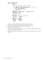
The critical resource analysis (CRA) performed while doing an attention button initiated replace action is very restrictive and the action will not complete-it will fail-to protect critical resources from being impacted. For finer control over CRA actions use pdweb or the olrad command. Refer to the Interface Card OL* Support Guide located on the Web at http://docs.hp.com for details. Removing and Replacing a PCI Smart Fan Assembly The PCI smart fan assembly is located in front of the PCI card cage. The fan assembly is a hot-swap component. See "Hot-Swap FRUs" (page 101) for a list and description of hot-swap FRUs. Figure 6-49 PCI Smart Fan Assembly Location Preliminary Procedures These procedures must be completed before removing the PCI smart fan assembly. 1. Identify the failed fan assembly. Table 6-4 (page 157) defines the fan LED states. 2. Connect to ground with a wrist strap. See "Electrostatic Discharge " (page 103) for more information. 3. Remove the top cover. See "Removing and Replacing Covers" (page 104). Table 6-4 Smart Fan Assembly LED Indications LED State On Green Flash Yellow Red Off Meaning Fan is at speed and in sync or not at speed less than 12 seconds. Fan is not keeping up with speed/sync pulse for greater than 12 seconds. Fan failed/stalled, has run slow, or fast for greater than 12 seconds. Fan is not present, or no power is applied to fan, or the fan has failed. Removing the PCI Smart Fan Assembly 1. Securely grasp the two thumb holds on the fan assembly. 2. Slide the fan upward from the chassis. Removing and Replacing a PCI Smart Fan Assembly 157
-
 1
1 -
2
-
3
-
4
-
5
-
6
-
7
-
8
-
9
-
10
-
11
-
12
-
13
-
14
-
15
-
16
-
17
-
18
-
19
-
20
-
21
-
22
-
23
-
24
-
25
-
26
-
27
-
28
-
29
-
30
-
31
-
32
-
33
-
34
-
35
-
36
-
37
-
38
-
39
-
40
-
41
-
42
-
43
-
44
-
45
-
46
-
47
-
48
-
49
-
50
-
51
-
52
-
53
-
54
-
55
-
56
-
57
-
58
-
59
-
60
-
61
-
62
-
63
-
64
-
65
-
66
-
67
-
68
-
69
-
70
-
71
-
72
-
73
-
74
-
75
-
76
-
77
-
78
-
79
-
80
-
81
-
82
-
83
-
84
-
85
-
86
-
87
-
88
-
89
-
90
-
91
-
92
-
93
-
94
-
95
-
96
-
97
-
98
-
99
-
100
-
101
-
102
-
103
-
104
-
105
-
106
-
107
-
108
-
109
-
110
-
111
-
112
-
113
-
114
-
115
-
116
-
117
-
118
-
119
-
120
-
121
-
122
-
123
-
124
-
125
-
126
-
127
-
128
-
129
-
130
-
131
-
132
-
133
-
134
-
135
-
136
-
137
-
138
-
139
-
140
-
141
-
142
-
143
-
144
-
145
-
146
-
147
-
148
-
149
-
150
-
151
-
 152
152 -
 153
153 -
 154
154 -
 155
155 -
 156
156 -
 157
157 -
 158
158 -
 159
159 -
 160
160 -
 161
161 -
 162
162 -
163
-
164
-
165
-
166
-
167
-
168
-
169
-
170
-
171
-
172
-
173
-
174
-
175
-
176
-
177
-
178
-
179
-
180
-
181
-
182
-
183
-
184
-
185
-
186
-
187
-
188
-
189
-
190
-
191
-
192
-
193
-
194
-
195
-
196
-
197
-
198
-
199
-
200
-
201
-
202
-
203
-
204
-
205
-
206
-
207
-
208
-
209
-
210
-
211
-
212
-
213
-
214
-
215
 |
 |
