HP rp8420 HP 9000 rp8420 Server - User Service Guide, Fifth Edition - Page 137
Removing and Replacing Covers Removing the Cell Board
 |
View all HP rp8420 manuals
Add to My Manuals
Save this manual to your list of manuals |
Page 137 highlights
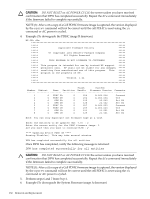
1. Remove the right side cover. See "Removing and Replacing Covers" (page 104). 2. Remove the cell board. See "Removing the Cell Board" (page 118). 3. Place the cell board on the ESD safe work surface. 4. Loosen the four captive thumb screws securing the removable DIMM cover. See Figure 6-26. Figure 6-26 DIMM Cover Assembly 5. Lift the cover to gain access to the DIMMs. Removing and Replacing DIMMs 137
-
 1
1 -
2
-
3
-
4
-
5
-
6
-
7
-
8
-
9
-
10
-
11
-
12
-
13
-
14
-
15
-
16
-
17
-
18
-
19
-
20
-
21
-
22
-
23
-
24
-
25
-
26
-
27
-
28
-
29
-
30
-
31
-
32
-
33
-
34
-
35
-
36
-
37
-
38
-
39
-
40
-
41
-
42
-
43
-
44
-
45
-
46
-
47
-
48
-
49
-
50
-
51
-
52
-
53
-
54
-
55
-
56
-
57
-
58
-
59
-
60
-
61
-
62
-
63
-
64
-
65
-
66
-
67
-
68
-
69
-
70
-
71
-
72
-
73
-
74
-
75
-
76
-
77
-
78
-
79
-
80
-
81
-
82
-
83
-
84
-
85
-
86
-
87
-
88
-
89
-
90
-
91
-
92
-
93
-
94
-
95
-
96
-
97
-
98
-
99
-
100
-
101
-
102
-
103
-
104
-
105
-
106
-
107
-
108
-
109
-
110
-
111
-
112
-
113
-
114
-
115
-
116
-
117
-
118
-
119
-
120
-
121
-
122
-
123
-
124
-
125
-
126
-
127
-
128
-
129
-
130
-
131
-
 132
132 -
 133
133 -
 134
134 -
 135
135 -
 136
136 -
 137
137 -
 138
138 -
 139
139 -
 140
140 -
 141
141 -
 142
142 -
143
-
144
-
145
-
146
-
147
-
148
-
149
-
150
-
151
-
152
-
153
-
154
-
155
-
156
-
157
-
158
-
159
-
160
-
161
-
162
-
163
-
164
-
165
-
166
-
167
-
168
-
169
-
170
-
171
-
172
-
173
-
174
-
175
-
176
-
177
-
178
-
179
-
180
-
181
-
182
-
183
-
184
-
185
-
186
-
187
-
188
-
189
-
190
-
191
-
192
-
193
-
194
-
195
-
196
-
197
-
198
-
199
-
200
-
201
-
202
-
203
-
204
-
205
-
206
-
207
-
208
-
209
-
210
-
211
-
212
-
213
-
214
-
215
 |
 |

1.
Remove the right side cover. See
“Removing and Replacing Covers” (page 104)
.
2.
Remove the cell board. See
“Removing the Cell Board” (page 118)
.
3.
Place the cell board on the ESD safe work surface.
4.
Loosen the four captive thumb screws securing the removable DIMM cover. See
Figure 6-26
.
Figure 6-26 DIMM Cover Assembly
5.
Lift the cover to gain access to the DIMMs.
Removing and Replacing DIMMs
137