HP rp8420 HP 9000 rp8420 Server - User Service Guide, Fifth Edition - Page 121
Cell Break-Fix Upgrade and Downgrade Procedure, Upgrading Using the FW Command
 |
View all HP rp8420 manuals
Add to My Manuals
Save this manual to your list of manuals |
Page 121 highlights
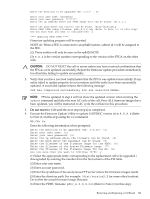
NOTE: The PDHC stateshould read Attention LED is off, and the Power Statusshould read RDY. If the Power Statusreads rdy, then one or both of the extraction levers are not properly locked. Ensure both cell board extraction levers are locked. Figure 6-21 shows a sample of the output. Figure 6-21 de Command Output 7. Replace the right side cover. See "Replacing the Side Cover" (page 107) for details. Cell Break-Fix Upgrade and Downgrade Procedure This release notice provides information, upgrade and downgrade instructions for the rp7420, rp8420, rx7620 and an rx8620 system products. These instructions pertain to a break fix scenario where a replacement cell is added to a currently operating system. Upgrading Using the FW Command The steps for upgrading the newly added cell using the FW command are as follows: 1. OSP the PDHC FPGA image to the new cell. 2. Firmware upgrade/downgrade the PDHC image to the new cell. 3. AC power cycle the Cell 4. Firmware upgrade/downgrade the System Firmware image to the new cell. Removing and Replacing a Cell Board 121
-
 1
1 -
2
-
3
-
4
-
5
-
6
-
7
-
8
-
9
-
10
-
11
-
12
-
13
-
14
-
15
-
16
-
17
-
18
-
19
-
20
-
21
-
22
-
23
-
24
-
25
-
26
-
27
-
28
-
29
-
30
-
31
-
32
-
33
-
34
-
35
-
36
-
37
-
38
-
39
-
40
-
41
-
42
-
43
-
44
-
45
-
46
-
47
-
48
-
49
-
50
-
51
-
52
-
53
-
54
-
55
-
56
-
57
-
58
-
59
-
60
-
61
-
62
-
63
-
64
-
65
-
66
-
67
-
68
-
69
-
70
-
71
-
72
-
73
-
74
-
75
-
76
-
77
-
78
-
79
-
80
-
81
-
82
-
83
-
84
-
85
-
86
-
87
-
88
-
89
-
90
-
91
-
92
-
93
-
94
-
95
-
96
-
97
-
98
-
99
-
100
-
101
-
102
-
103
-
104
-
105
-
106
-
107
-
108
-
109
-
110
-
111
-
112
-
113
-
114
-
115
-
 116
116 -
 117
117 -
 118
118 -
 119
119 -
 120
120 -
 121
121 -
 122
122 -
 123
123 -
 124
124 -
 125
125 -
 126
126 -
127
-
128
-
129
-
130
-
131
-
132
-
133
-
134
-
135
-
136
-
137
-
138
-
139
-
140
-
141
-
142
-
143
-
144
-
145
-
146
-
147
-
148
-
149
-
150
-
151
-
152
-
153
-
154
-
155
-
156
-
157
-
158
-
159
-
160
-
161
-
162
-
163
-
164
-
165
-
166
-
167
-
168
-
169
-
170
-
171
-
172
-
173
-
174
-
175
-
176
-
177
-
178
-
179
-
180
-
181
-
182
-
183
-
184
-
185
-
186
-
187
-
188
-
189
-
190
-
191
-
192
-
193
-
194
-
195
-
196
-
197
-
198
-
199
-
200
-
201
-
202
-
203
-
204
-
205
-
206
-
207
-
208
-
209
-
210
-
211
-
212
-
213
-
214
-
215
 |
 |
