HP rp8420 HP 9000 rp8420 Server - User Service Guide, Fifth Edition - Page 90
Interlock Switches, Disk Drive LEDs, LAN Default Parameters, RS-232 Serial Port Default Parameters
 |
View all HP rp8420 manuals
Add to My Manuals
Save this manual to your list of manuals |
Page 90 highlights
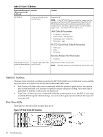
Table 5-8 Core I/O Buttons Button Identification (as Location silk-screened on the bulkhead) MP RESET To the far left side of the core I/O card Function Resets the MP NOTE: If the MP RESET button is held for longer than five seconds, it will clear the MP password and reset the LAN, RS-232 (serial port), and modem port parameters to their default values. The default password for the MP is Admin (upper case A intended) when the MP is reset. LAN Default Parameters • IP Address-192.168.1.1 • Subnet mask-255.255.255.0 • Default gateway-192.168.1.1 • Hostname-gsp0 RS-232 (Serial Port) Default Parameters • 9600 baud • 8 bits • No parity Remote/Modem Port Parameters • Disabled OLR (Symbol next to To the far right side of the Request OL* for this core I/O slot button is shown below) core I/O card NOTE: The OLR function is not enabled for the core I/O card. Interlock Switches There are three interlock switches located in the HP 9000 rp8420 server. Both side covers and the top cover have an interlock switch located underneath each cover. • Side Covers-If either side cover is removed while the system is powered on, the system fans on the front and rear increase in speed to ensure adequate cooling. An event code is generated to indicate a side cover was removed. • Top Cover-If the top cover is removed while the system power is on, the PCI-X card cage assembly I/O fan speed will not change. An event code is generated to indicate the top cover was removed. Disk Drive LEDs There are two tri-color LED on each disk drive. Figure 5-9 Disk Drive LED Location 90 Troubleshooting
-
 1
1 -
2
-
3
-
4
-
5
-
6
-
7
-
8
-
9
-
10
-
11
-
12
-
13
-
14
-
15
-
16
-
17
-
18
-
19
-
20
-
21
-
22
-
23
-
24
-
25
-
26
-
27
-
28
-
29
-
30
-
31
-
32
-
33
-
34
-
35
-
36
-
37
-
38
-
39
-
40
-
41
-
42
-
43
-
44
-
45
-
46
-
47
-
48
-
49
-
50
-
51
-
52
-
53
-
54
-
55
-
56
-
57
-
58
-
59
-
60
-
61
-
62
-
63
-
64
-
65
-
66
-
67
-
68
-
69
-
70
-
71
-
72
-
73
-
74
-
75
-
76
-
77
-
78
-
79
-
80
-
81
-
82
-
83
-
84
-
 85
85 -
 86
86 -
 87
87 -
 88
88 -
 89
89 -
 90
90 -
 91
91 -
 92
92 -
 93
93 -
 94
94 -
 95
95 -
96
-
97
-
98
-
99
-
100
-
101
-
102
-
103
-
104
-
105
-
106
-
107
-
108
-
109
-
110
-
111
-
112
-
113
-
114
-
115
-
116
-
117
-
118
-
119
-
120
-
121
-
122
-
123
-
124
-
125
-
126
-
127
-
128
-
129
-
130
-
131
-
132
-
133
-
134
-
135
-
136
-
137
-
138
-
139
-
140
-
141
-
142
-
143
-
144
-
145
-
146
-
147
-
148
-
149
-
150
-
151
-
152
-
153
-
154
-
155
-
156
-
157
-
158
-
159
-
160
-
161
-
162
-
163
-
164
-
165
-
166
-
167
-
168
-
169
-
170
-
171
-
172
-
173
-
174
-
175
-
176
-
177
-
178
-
179
-
180
-
181
-
182
-
183
-
184
-
185
-
186
-
187
-
188
-
189
-
190
-
191
-
192
-
193
-
194
-
195
-
196
-
197
-
198
-
199
-
200
-
201
-
202
-
203
-
204
-
205
-
206
-
207
-
208
-
209
-
210
-
211
-
212
-
213
-
214
-
215
 |
 |
