HP rp8420 HP 9000 rp8420 Server - User Service Guide, Fifth Edition - Page 153
Replacing the Core I/O Assembly, Configuring MP Network Settings, Core I/O Detail
 |
View all HP rp8420 manuals
Add to My Manuals
Save this manual to your list of manuals |
Page 153 highlights
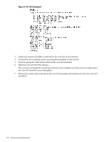
Figure 6-46 Core I/O Detail Replacing the Core I/O Assembly 1. Locate the battery on the new MP. Remove the insulating mylar strip. If there is no mylar strip then momentarily break the battery connection to clear any previously stored data that could conflict with your current configuration. 2. Slide the core I/O into the chassis while rocking it gently up and down to mate the two connectors. 3. Tighten the two retaining screws securing the assembly to the chassis. 4. Connect the cables that were labeled and detached during removal of the core I/O. 5. Reset the nPartition with the MP RR command. This command will stop the boot process at BIB and allow you to check the firmware revision of the new MP. Update or backdate as needed. Configure the network settings as outlined in the following section. Configuring MP Network Settings After removing and replacing the core I/O in the server, configure its customer LAN network settings, using the settings from the original (replaced) core I/O. To configure MP network settings, use the MP Command menu's LC command. To list the current MP network configuration, use the LS command. Default Management Processor Network Settings Table 6-3 lists the default customer LAN network settings for the server. Table 6-3 Default Configuration for Management Processor Customer LAN Customer LAN IP Address Customer LAN Host Name Customer LAN Subnet Mask Customer LAN Gateway 192.168.1.1 gsp0 255.255.255.0 192.168.1.1 Removing and Replacing the Core I/O 153
-
 1
1 -
2
-
3
-
4
-
5
-
6
-
7
-
8
-
9
-
10
-
11
-
12
-
13
-
14
-
15
-
16
-
17
-
18
-
19
-
20
-
21
-
22
-
23
-
24
-
25
-
26
-
27
-
28
-
29
-
30
-
31
-
32
-
33
-
34
-
35
-
36
-
37
-
38
-
39
-
40
-
41
-
42
-
43
-
44
-
45
-
46
-
47
-
48
-
49
-
50
-
51
-
52
-
53
-
54
-
55
-
56
-
57
-
58
-
59
-
60
-
61
-
62
-
63
-
64
-
65
-
66
-
67
-
68
-
69
-
70
-
71
-
72
-
73
-
74
-
75
-
76
-
77
-
78
-
79
-
80
-
81
-
82
-
83
-
84
-
85
-
86
-
87
-
88
-
89
-
90
-
91
-
92
-
93
-
94
-
95
-
96
-
97
-
98
-
99
-
100
-
101
-
102
-
103
-
104
-
105
-
106
-
107
-
108
-
109
-
110
-
111
-
112
-
113
-
114
-
115
-
116
-
117
-
118
-
119
-
120
-
121
-
122
-
123
-
124
-
125
-
126
-
127
-
128
-
129
-
130
-
131
-
132
-
133
-
134
-
135
-
136
-
137
-
138
-
139
-
140
-
141
-
142
-
143
-
144
-
145
-
146
-
147
-
 148
148 -
 149
149 -
 150
150 -
 151
151 -
 152
152 -
 153
153 -
 154
154 -
 155
155 -
 156
156 -
 157
157 -
 158
158 -
159
-
160
-
161
-
162
-
163
-
164
-
165
-
166
-
167
-
168
-
169
-
170
-
171
-
172
-
173
-
174
-
175
-
176
-
177
-
178
-
179
-
180
-
181
-
182
-
183
-
184
-
185
-
186
-
187
-
188
-
189
-
190
-
191
-
192
-
193
-
194
-
195
-
196
-
197
-
198
-
199
-
200
-
201
-
202
-
203
-
204
-
205
-
206
-
207
-
208
-
209
-
210
-
211
-
212
-
213
-
214
-
215
 |
 |
