HP rp8420 HP 9000 rp8420 Server - User Service Guide, Fifth Edition - Page 99
Verifying Cell Board Insertion, Cell Board Extraction Levers
 |
View all HP rp8420 manuals
Add to My Manuals
Save this manual to your list of manuals |
Page 99 highlights
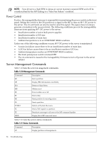
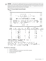
Figure 5-13 HP 9000 rp8420 server Cabinet FRUs (Rear View) Verifying Cell Board Insertion Cell Board Extraction Levers It is important that both extraction levers on the cell board be in the locked position. Both levers must be locked for the cell board to power up and function properly. Power to the cell board should only be removed using the MP:CM>PE command or by shutting down the partition or server. Therefore, if the levers become unlocked, the partition will not have a chance to logically shut down, and damage could occur to the operating system. If the cell board is powered on and one lever becomes unlocked, the cell board will stay powered on. However, if the cell board is powered off, it will not power on again until both levers are in the locked position. The lever status can be determined by issuing the MP:CM>DE command and viewing the power status of the cell board controller (PDHC). The "ready" bit will only be true when both levers are locked and all VRMs are installed. This status can be used to determine if both levers are locked and the cell board is properly installed in the chassis. See Figure 5-14 (page 100) for a sample of the output. If the state is "RDY" denoted by capital letters in the computer output then the "ready bit" is true. If the state is "rdy" as denoted by lower case letters in the computer output then the "ready bit" is false. Refer to Table 5-13 for details. Verifying Cell Board Insertion 99
-
 1
1 -
2
-
3
-
4
-
5
-
6
-
7
-
8
-
9
-
10
-
11
-
12
-
13
-
14
-
15
-
16
-
17
-
18
-
19
-
20
-
21
-
22
-
23
-
24
-
25
-
26
-
27
-
28
-
29
-
30
-
31
-
32
-
33
-
34
-
35
-
36
-
37
-
38
-
39
-
40
-
41
-
42
-
43
-
44
-
45
-
46
-
47
-
48
-
49
-
50
-
51
-
52
-
53
-
54
-
55
-
56
-
57
-
58
-
59
-
60
-
61
-
62
-
63
-
64
-
65
-
66
-
67
-
68
-
69
-
70
-
71
-
72
-
73
-
74
-
75
-
76
-
77
-
78
-
79
-
80
-
81
-
82
-
83
-
84
-
85
-
86
-
87
-
88
-
89
-
90
-
91
-
92
-
93
-
 94
94 -
 95
95 -
 96
96 -
 97
97 -
 98
98 -
 99
99 -
 100
100 -
 101
101 -
 102
102 -
 103
103 -
 104
104 -
105
-
106
-
107
-
108
-
109
-
110
-
111
-
112
-
113
-
114
-
115
-
116
-
117
-
118
-
119
-
120
-
121
-
122
-
123
-
124
-
125
-
126
-
127
-
128
-
129
-
130
-
131
-
132
-
133
-
134
-
135
-
136
-
137
-
138
-
139
-
140
-
141
-
142
-
143
-
144
-
145
-
146
-
147
-
148
-
149
-
150
-
151
-
152
-
153
-
154
-
155
-
156
-
157
-
158
-
159
-
160
-
161
-
162
-
163
-
164
-
165
-
166
-
167
-
168
-
169
-
170
-
171
-
172
-
173
-
174
-
175
-
176
-
177
-
178
-
179
-
180
-
181
-
182
-
183
-
184
-
185
-
186
-
187
-
188
-
189
-
190
-
191
-
192
-
193
-
194
-
195
-
196
-
197
-
198
-
199
-
200
-
201
-
202
-
203
-
204
-
205
-
206
-
207
-
208
-
209
-
210
-
211
-
212
-
213
-
214
-
215
 |
 |
