HP rp8420 HP 9000 rp8420 Server - User Service Guide, Fifth Edition - Page 36
backplane near the connectors that attach the core I/O boards.
 |
View all HP rp8420 manuals
Add to My Manuals
Save this manual to your list of manuals |
Page 36 highlights
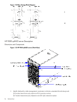
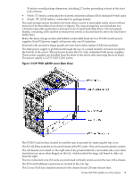
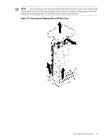
Redundant line cords attach to the AC power receptacles at the bottom rear. Two 20-amp cords are required to power the HP 9000 rp8420 server. Two additional line cords provide redundancy. Access the system backplane by removing the left side cover. The system backplane hinges from the lower edge and is anchored at the top with a single large jack screw assembly. The SCSI ribbon cable assembly also routes across and fastens to the backside of the system backplane near the connectors that attach the core I/O boards. The blue deployment handles hinge outward to help lift and move the server into a rack. 36 Introduction
-
 1
1 -
2
-
3
-
4
-
5
-
6
-
7
-
8
-
9
-
10
-
11
-
12
-
13
-
14
-
15
-
16
-
17
-
18
-
19
-
20
-
21
-
22
-
23
-
24
-
25
-
26
-
27
-
28
-
29
-
30
-
 31
31 -
 32
32 -
 33
33 -
 34
34 -
 35
35 -
 36
36 -
 37
37 -
 38
38 -
 39
39 -
 40
40 -
 41
41 -
42
-
43
-
44
-
45
-
46
-
47
-
48
-
49
-
50
-
51
-
52
-
53
-
54
-
55
-
56
-
57
-
58
-
59
-
60
-
61
-
62
-
63
-
64
-
65
-
66
-
67
-
68
-
69
-
70
-
71
-
72
-
73
-
74
-
75
-
76
-
77
-
78
-
79
-
80
-
81
-
82
-
83
-
84
-
85
-
86
-
87
-
88
-
89
-
90
-
91
-
92
-
93
-
94
-
95
-
96
-
97
-
98
-
99
-
100
-
101
-
102
-
103
-
104
-
105
-
106
-
107
-
108
-
109
-
110
-
111
-
112
-
113
-
114
-
115
-
116
-
117
-
118
-
119
-
120
-
121
-
122
-
123
-
124
-
125
-
126
-
127
-
128
-
129
-
130
-
131
-
132
-
133
-
134
-
135
-
136
-
137
-
138
-
139
-
140
-
141
-
142
-
143
-
144
-
145
-
146
-
147
-
148
-
149
-
150
-
151
-
152
-
153
-
154
-
155
-
156
-
157
-
158
-
159
-
160
-
161
-
162
-
163
-
164
-
165
-
166
-
167
-
168
-
169
-
170
-
171
-
172
-
173
-
174
-
175
-
176
-
177
-
178
-
179
-
180
-
181
-
182
-
183
-
184
-
185
-
186
-
187
-
188
-
189
-
190
-
191
-
192
-
193
-
194
-
195
-
196
-
197
-
198
-
199
-
200
-
201
-
202
-
203
-
204
-
205
-
206
-
207
-
208
-
209
-
210
-
211
-
212
-
213
-
214
-
215
 |
 |

Redundant line cords attach to the AC power receptacles at the bottom rear. Two 20-amp cords
are required to power the HP 9000 rp8420 server. Two additional line cords provide redundancy.
Access the system backplane by removing the left side cover. The system backplane hinges from
the lower edge and is anchored at the top with a single large jack screw assembly.
The SCSI ribbon cable assembly also routes across and fastens to the backside of the system
backplane near the connectors that attach the core I/O boards.
The blue deployment handles hinge outward to help lift and move the server into a rack.
36
Introduction