HP rp8420 HP 9000 rp8420 Server - User Service Guide, Fifth Edition - Page 62
Connecting AC Input Power, Wall Receptacle Pinouts, WARNING
 |
View all HP rp8420 manuals
Add to My Manuals
Save this manual to your list of manuals |
Page 62 highlights
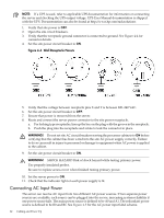
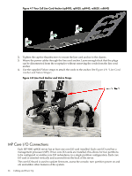
NOTE: If a UPS is used, refer to applicable UPS documentation for information on connecting the server and checking the UPS output voltage. UPS User Manual documentation is shipped with the UPS. Documentation can also be found at http://www.hp.com/racksolutions 1. Verify that site power is OFF. 2. Open the site circuit breakers. 3. Verify that the receptacle ground connector is connected to ground. See Figure 4-4 for connector details. 4. Set the site power circuit breaker to ON. Figure 4-4 Wall Receptacle Pinouts 5. Verify that the voltage between receptacle pins X and Y is between 200-240 VAC. 6. Set the site power circuit breaker to OFF. 7. Ensure that power is removed from the server. 8. Route and connect the server power connector to the site power receptacle. a. For locking type receptacles, line up the key on the plug with the groove in the receptacle. b. Push the plug into the receptacle and rotate to lock the connector in place. WARNING! Do not set site AC circuit breakers serving the processor cabinets to ON before verifying that the cabinet has been wired into the site AC power supply correctly. Failure to do so can result in injury to personnel or damage to equipment when AC power is applied to the cabinet. 9. Set the site power circuit breaker to ON. WARNING! SHOCK HAZARD Risk of shock hazard while testing primary power. Use properly insulated probes. Be sure to replace access cover when finished testing primary power. 10. Set the server power to ON. 11. Check that the indicator light on each power supply is lit. Connecting AC Input Power The server can receive AC input from two different AC power sources. If two separate power sources are available, each source can be plugged into the server, increasing system reliability if one power source fails. The main power source is defined to be A0 and A1. The redundant power source is defined to be B0 and B1. See Figure 4-5 for the AC power input label scheme. 62 Cabling and Power Up
-
 1
1 -
2
-
3
-
4
-
5
-
6
-
7
-
8
-
9
-
10
-
11
-
12
-
13
-
14
-
15
-
16
-
17
-
18
-
19
-
20
-
21
-
22
-
23
-
24
-
25
-
26
-
27
-
28
-
29
-
30
-
31
-
32
-
33
-
34
-
35
-
36
-
37
-
38
-
39
-
40
-
41
-
42
-
43
-
44
-
45
-
46
-
47
-
48
-
49
-
50
-
51
-
52
-
53
-
54
-
55
-
56
-
 57
57 -
 58
58 -
 59
59 -
 60
60 -
 61
61 -
 62
62 -
 63
63 -
 64
64 -
 65
65 -
 66
66 -
 67
67 -
68
-
69
-
70
-
71
-
72
-
73
-
74
-
75
-
76
-
77
-
78
-
79
-
80
-
81
-
82
-
83
-
84
-
85
-
86
-
87
-
88
-
89
-
90
-
91
-
92
-
93
-
94
-
95
-
96
-
97
-
98
-
99
-
100
-
101
-
102
-
103
-
104
-
105
-
106
-
107
-
108
-
109
-
110
-
111
-
112
-
113
-
114
-
115
-
116
-
117
-
118
-
119
-
120
-
121
-
122
-
123
-
124
-
125
-
126
-
127
-
128
-
129
-
130
-
131
-
132
-
133
-
134
-
135
-
136
-
137
-
138
-
139
-
140
-
141
-
142
-
143
-
144
-
145
-
146
-
147
-
148
-
149
-
150
-
151
-
152
-
153
-
154
-
155
-
156
-
157
-
158
-
159
-
160
-
161
-
162
-
163
-
164
-
165
-
166
-
167
-
168
-
169
-
170
-
171
-
172
-
173
-
174
-
175
-
176
-
177
-
178
-
179
-
180
-
181
-
182
-
183
-
184
-
185
-
186
-
187
-
188
-
189
-
190
-
191
-
192
-
193
-
194
-
195
-
196
-
197
-
198
-
199
-
200
-
201
-
202
-
203
-
204
-
205
-
206
-
207
-
208
-
209
-
210
-
211
-
212
-
213
-
214
-
215
 |
 |
