HP rp8420 HP 9000 rp8420 Server - User Service Guide, Fifth Edition - Page 138
Removing a DIMM, Configuration restrictions apply when installing 4 GB DIMMs. 4 GB DIMMs
 |
View all HP rp8420 manuals
Add to My Manuals
Save this manual to your list of manuals |
Page 138 highlights
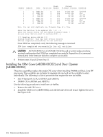
Removing a DIMM 1. Identify the defective DIMMs using Figure 6-27 to aid with DIMM location on cell board. Figure 6-27 DIMM Detail with Locations 2. Using both DIMM removal tools, place the grooved side of each tool on each side of the target DIMM. See Figure 6-28. Figure 6-28 DIMM Removal Tools 3. Seat the tool tips down to limit, then leverage connector latches outward to unseat the DIMM from the memory slot. Replacing a DIMM IMPORTANT: Configuration restrictions apply when installing 4 GB DIMMs. 4 GB DIMMs cannot be mixed with any other sized DIMMs on the same cell board. However, 4 GB DIMMs can be mixed with other sized DIMMs within the same nPartition as long as they are not mixed on the same cell board. 1. Orient the replacement DIMM connector key over the memory slot. 138 Removal and Replacement
-
 1
1 -
2
-
3
-
4
-
5
-
6
-
7
-
8
-
9
-
10
-
11
-
12
-
13
-
14
-
15
-
16
-
17
-
18
-
19
-
20
-
21
-
22
-
23
-
24
-
25
-
26
-
27
-
28
-
29
-
30
-
31
-
32
-
33
-
34
-
35
-
36
-
37
-
38
-
39
-
40
-
41
-
42
-
43
-
44
-
45
-
46
-
47
-
48
-
49
-
50
-
51
-
52
-
53
-
54
-
55
-
56
-
57
-
58
-
59
-
60
-
61
-
62
-
63
-
64
-
65
-
66
-
67
-
68
-
69
-
70
-
71
-
72
-
73
-
74
-
75
-
76
-
77
-
78
-
79
-
80
-
81
-
82
-
83
-
84
-
85
-
86
-
87
-
88
-
89
-
90
-
91
-
92
-
93
-
94
-
95
-
96
-
97
-
98
-
99
-
100
-
101
-
102
-
103
-
104
-
105
-
106
-
107
-
108
-
109
-
110
-
111
-
112
-
113
-
114
-
115
-
116
-
117
-
118
-
119
-
120
-
121
-
122
-
123
-
124
-
125
-
126
-
127
-
128
-
129
-
130
-
131
-
132
-
 133
133 -
 134
134 -
 135
135 -
 136
136 -
 137
137 -
 138
138 -
 139
139 -
 140
140 -
 141
141 -
 142
142 -
 143
143 -
144
-
145
-
146
-
147
-
148
-
149
-
150
-
151
-
152
-
153
-
154
-
155
-
156
-
157
-
158
-
159
-
160
-
161
-
162
-
163
-
164
-
165
-
166
-
167
-
168
-
169
-
170
-
171
-
172
-
173
-
174
-
175
-
176
-
177
-
178
-
179
-
180
-
181
-
182
-
183
-
184
-
185
-
186
-
187
-
188
-
189
-
190
-
191
-
192
-
193
-
194
-
195
-
196
-
197
-
198
-
199
-
200
-
201
-
202
-
203
-
204
-
205
-
206
-
207
-
208
-
209
-
210
-
211
-
212
-
213
-
214
-
215
 |
 |
