HP rp8420 HP 9000 rp8420 Server - User Service Guide, Fifth Edition - Page 170
Removing and Replacing a BPS, Reconnect core I/O cards.
 |
View all HP rp8420 manuals
Add to My Manuals
Save this manual to your list of manuals |
Page 170 highlights
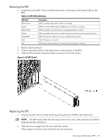
3. Tilt the backplane forward until it is resting against the chassis. Ensure all cables are correctly routed to the outer side of the backplane to avoid damage to the cables. Tighten the jack screw (eight to nine turns to tighten). CAUTION: Watch for system board flex when tightening the jack screw. Over-compression will destroy the backplane. 4. Reconnect all cables. 5. Reconnect core I/O cards. 6. Reconnect all cell boards. 7. Replace all covers. See "Removing and Replacing Covers" (page 104). 8. Plug in the power cords and power on the system. 9. Check status with the PS command by selecting S for the system backplane. Removing and Replacing a BPS The BPS is located in the front of the chassis. The BPS is a hot-swap component. See "Hot-Swap FRUs" (page 101) for a list and description of hot-swap FRUs. Figure 6-64 BPS Location (Front Bezel Removed) 170 Removal and Replacement
-
 1
1 -
2
-
3
-
4
-
5
-
6
-
7
-
8
-
9
-
10
-
11
-
12
-
13
-
14
-
15
-
16
-
17
-
18
-
19
-
20
-
21
-
22
-
23
-
24
-
25
-
26
-
27
-
28
-
29
-
30
-
31
-
32
-
33
-
34
-
35
-
36
-
37
-
38
-
39
-
40
-
41
-
42
-
43
-
44
-
45
-
46
-
47
-
48
-
49
-
50
-
51
-
52
-
53
-
54
-
55
-
56
-
57
-
58
-
59
-
60
-
61
-
62
-
63
-
64
-
65
-
66
-
67
-
68
-
69
-
70
-
71
-
72
-
73
-
74
-
75
-
76
-
77
-
78
-
79
-
80
-
81
-
82
-
83
-
84
-
85
-
86
-
87
-
88
-
89
-
90
-
91
-
92
-
93
-
94
-
95
-
96
-
97
-
98
-
99
-
100
-
101
-
102
-
103
-
104
-
105
-
106
-
107
-
108
-
109
-
110
-
111
-
112
-
113
-
114
-
115
-
116
-
117
-
118
-
119
-
120
-
121
-
122
-
123
-
124
-
125
-
126
-
127
-
128
-
129
-
130
-
131
-
132
-
133
-
134
-
135
-
136
-
137
-
138
-
139
-
140
-
141
-
142
-
143
-
144
-
145
-
146
-
147
-
148
-
149
-
150
-
151
-
152
-
153
-
154
-
155
-
156
-
157
-
158
-
159
-
160
-
161
-
162
-
163
-
164
-
 165
165 -
 166
166 -
 167
167 -
 168
168 -
 169
169 -
 170
170 -
 171
171 -
 172
172 -
 173
173 -
 174
174 -
 175
175 -
176
-
177
-
178
-
179
-
180
-
181
-
182
-
183
-
184
-
185
-
186
-
187
-
188
-
189
-
190
-
191
-
192
-
193
-
194
-
195
-
196
-
197
-
198
-
199
-
200
-
201
-
202
-
203
-
204
-
205
-
206
-
207
-
208
-
209
-
210
-
211
-
212
-
213
-
214
-
215
 |
 |
