IBM 4851 514 Service Guide
IBM 4851 514 Manual
 |
View all IBM 4851 514 manuals
Add to My Manuals
Save this manual to your list of manuals |
IBM 4851 514 manual content summary:
- IBM 4851 514 | Service Guide - Page 1
SurePOS 500 Series Planning, Installation and Service Guide Model 514 Updated October, 2008 GA27-4361-01 - IBM 4851 514 | Service Guide - Page 2
- IBM 4851 514 | Service Guide - Page 3
SurePOS 500 Series Planning, Installation and Service Guide Model 514 Updated October, 2008 GA27-4361-01 - IBM 4851 514 | Service Guide - Page 4
Before using this information and the product it supports, be sure to read the Appendix D, "Safety information," and the general information under Appendix C, "Notices." Second Edition (June 2006) This edition applies to the IBM SurePOS 500 Model 514 and to all subsequent releases and modifications - IBM 4851 514 | Service Guide - Page 5
00 (February, 2006 xiii Chapter 1. Introducing the SurePOS 500 Model 514 1 Architectural attributes 2 Models and features 2 Optional features 3 Supported operating systems 3 Calling for service 3 Chapter 2. Installing the IBM SurePOS 500 Model 514 5 Rear view and connectors 5 Installation - IBM 4851 514 | Service Guide - Page 6
panel (tailgate) with fan - removing and replacing . . . . . 64 System board - removing and replacing 66 Memory modules - removing and replacing 68 Power 87 How to use the parts catalog 87 Assembly 1: SurePOS 500 (4851) Model 514 88 Assembly 2: Display tablet components 90 | Assembly - IBM 4851 514 | Service Guide - Page 7
Updated October, 2008 Appendix C. Notices 113 Intel software license agreement (final, single user 115 Important - read before copying, installing or using 115 Electronic emission notices 116 Federal Communications Commission (FCC) statement 116 Industry Canada Class A Emission Compliance - IBM 4851 514 | Service Guide - Page 8
Updated October, 2008 vi SurePOS 500 Model 514 - IBM 4851 514 | Service Guide - Page 9
October, 2008 Figures 1. IBM SurePOS 500 Model 514 and supported devices 1 2. Serial number location 4 3. IBM 4851 connectors 5 4. Memory module display cable 42 34. Attaching the distributed customer display to the system unit 43 35. Installing the distributed customer display onto the - IBM 4851 514 | Service Guide - Page 10
68. Removing and replacing the top cover 82 69. Keylock assembly 82 70. Cash-drawer latch and sensor assembly 83 71. Lock accessories 84 viii SurePOS 500 Model 514 - IBM 4851 514 | Service Guide - Page 11
1. Architecture summary 2 2. Model 514 models 2 3. IBM Model 514 hardware options 3 4. Rear view System board jumper settings 68 11. Power cords 102 12. SurePOS 500 Model 514 dimensions 104 13. SurePOS 500 Model 514 weights 104 14. Input voltage, frequency 107 15. SurePOS 500 Model 514 - IBM 4851 514 | Service Guide - Page 12
Updated October, 2008 x SurePOS 500 Model 514 - IBM 4851 514 | Service Guide - Page 13
retail/store/. From this page, click Support. v IBM SurePOS 500 Model 514 Operating System Installation Guide, GA27-4362 | v IBM Point of Sale Options and I/O Devices Service Guide, GC30-9737 v IBM Safety Information, GA27-4004 System software, touch drivers, and diagnostics You can obtain the - IBM 4851 514 | Service Guide - Page 14
this guide is available on the Publications Web page: www.ibm.com/solutions/retail/store/. Click Support, then Publications. Accessibility Accessibility features help a user who has a physical disability, such as restricted mobility or limited vision, to use the SurePOS 500 Model 514 successfully - IBM 4851 514 | Service Guide - Page 15
assembly update. | GA27-4361-01 (June, 2006) | This update removes parts listings that have been moved to the IBM Point of Sale | Options and I/O Devices Service Guide, GC30-9737 | Changed or new information is indicated by a revision character (|) in the left | margin. Web-only update - IBM 4851 514 | Service Guide - Page 16
Updated October, 2008 xiv SurePOS 500 Model 514 - IBM 4851 514 | Service Guide - Page 17
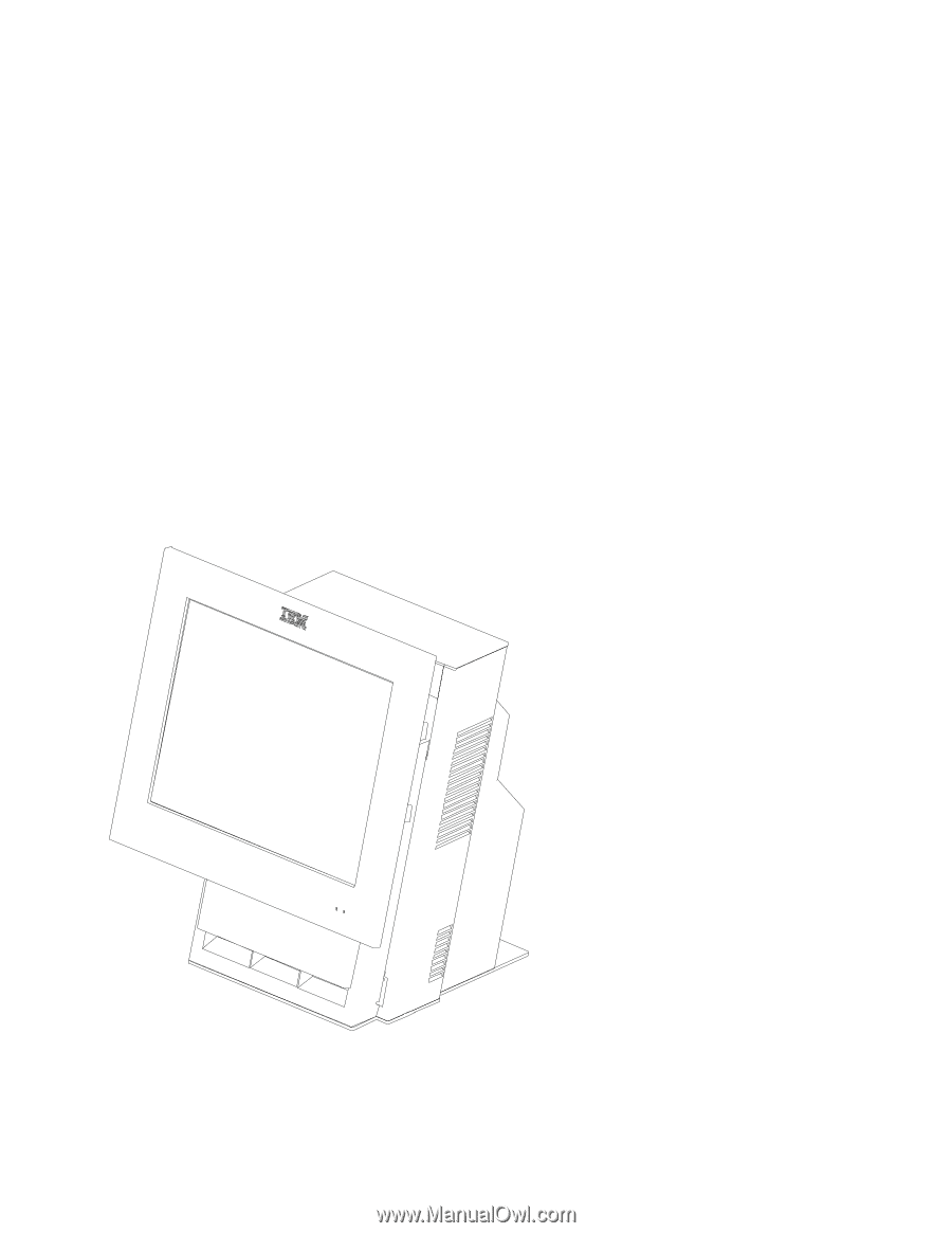
1. Introducing the SurePOS 500 Model 514 The IBM SurePOS 4851, Model 514 enables you to provide fast, accurate customer service and to manage your restaurant or store efficiently. Designed for the food service specialties, the system supports a wide variety of both IBM and non-IBM input/output - IBM 4851 514 | Service Guide - Page 18
system has two DIMM slots and supports 4851-E14 System unit Model 514, preloaded with the Windows XP Embedded for Point of Service 4951-514 Express bundle; dependant upon country, could include: v Integrated MSR v Integrated customer display v 4610 printer and cash drawer 2 SurePOS 500 Model 514 - IBM 4851 514 | Service Guide - Page 19
IBM SurePOS 500 Model 514 supports these operating systems: v Windows™ XP, and 2000 Note: Windows DBCS versions (Japanese/Korean/Chinese) are also supported. v IBM Retail Environment for SUSE LINUX® (IRES) v DOS 2000 v Windows Embedded Point of Service (WEPOS) Calling for service When you call IBM - IBM 4851 514 | Service Guide - Page 20
Updated October, 2008 Figure 2. Serial number location 4 SurePOS 500 Model 514 - IBM 4851 514 | Service Guide - Page 21
procedures for setting up the SurePOS 500 Model 514 product. You should be familiar with the connectors of the IBM 4851 before you begin the installation steps. Rear view and connectors Figure 3 shows the SurePOS 500 Model 514 connectors. Figure 3. IBM 4851 connectors Table 4. Rear view connectors - IBM 4851 514 | Service Guide - Page 22
SurePOS 500 Model 514 on your mounting option (see Chapter 3, "Mounting the SurePOS 500 Model 514," on page 17). 3. Power on the system to IBM SurePOS Model 514 Operating System Installation Guide. Installing on page 119. The system board provides two memory-module sockets and supports up to 1 GB in - IBM 4851 514 | Service Guide - Page 23
Updated October, 2008 Installing the IBM SurePOS 500 Model 514 Figure 4. Memory module location 4. Touching only the top corners of the module, align the connector tabs and press the module down firmly. The white tabs - IBM 4851 514 | Service Guide - Page 24
IBM SurePOS 500 Model 514 Updated October, 2008 Retainer Figure 5. Memory module removal and insertion 5. Replace the rear inner metal cover. 6. Replace the rear cover (see "Rear cover - removing and replacing" on page 61). Installing the MSR Two types of MSRs can attach to the SurePOS 500 system - IBM 4851 514 | Service Guide - Page 25
Updated October, 2008 Installing the IBM SurePOS 500 Model 514 Figure 6. Installing the magnetic stripe reader (MSR) customer display Use the steps in this procedure to install the integrated customer display to the system. 1. Remove the rear cover. See "Rear cover - removing and replacing" on page - IBM 4851 514 | Service Guide - Page 26
the IBM SurePOS 500 Model 514 Updated October, 2008 Figure 7. Routing the integrated display cables 4. See Figure 7. Insert the integrated customer display cable into the hole ( A ) in the top of the unit. 5. Connect the cable to the system board location ( B ) at the upper right. 10 SurePOS 500 - IBM 4851 514 | Service Guide - Page 27
Updated October, 2008 Installing the IBM SurePOS 500 Model 514 Figure 8. Installing the integrated customer display 6. Snap the integrated customer display onto the top of the system unit in place of the top cover. 7. Reinstall the rear inner metal cover and rear cover. Installing the wireless - IBM 4851 514 | Service Guide - Page 28
Installing the IBM SurePOS 500 Model 514 Updated October, 2008 a. See A in Figure 9 on view the connectors and for information on routing. Connect the I/O cables. 3. Route the cables as instructed in "Routing and connecting cables to the rear connector panel." Routing and connecting cables to the - IBM 4851 514 | Service Guide - Page 29
Updated October, 2008 Installing the IBM SurePOS 500 Model 514 Figure 11. Cable routing label 1. Connect the cables as shown in as shown rear connector panel cables exiting through the hole. Allow sufficient length for cleaning and servicing. Chapter 2. Installing the IBM SurePOS 500 Model 514 13 - IBM 4851 514 | Service Guide - Page 30
Installing the IBM SurePOS 500 Model 514 Updated October, 2008 Powering on and the LED states 1. Plug the power cord into the SurePOS 500 Model 514 and then plug into an electrical outlet. Figure 12. Location of power switch and screen brightness adjusting buttons 2. Power on the system using the - IBM 4851 514 | Service Guide - Page 31
utility. For additional information, see the IBM SurePOS 500 Model 514 Operating System Installation Guide. To calibrate the touch screen: 1. Switch the power ON. 2. Touch the screen three times to enter the calibration mode. 3. Follow the instructions on the screen to calibrate the touch - IBM 4851 514 | Service Guide - Page 32
Installing the IBM SurePOS 500 Model 514 Updated October, 2008 16 SurePOS 500 Model 514 - IBM 4851 514 | Service Guide - Page 33
Mounting a distributed customer display and APA display to a cash drawer 42 Installing IBM 4610 SureMark Models TF6 or TF7 printers 44 Table 5 describes the various mounting configurations of the SurePOS 500 Model 514. Table 5. Mounting configurations To mount using the base to the countertop, see - IBM 4851 514 | Service Guide - Page 34
Mounting the SurePOS 500 Model 514 Table 5. Mounting configurations (continued) To mount to a countertop using the non-keyboard-integration tray, see "Countertop with non- 2008 To mount on a cash drawer using the non-keyboard-integration tray, see "Cash drawer" on page 28. 18 SurePOS 500 Model 514 - IBM 4851 514 | Service Guide - Page 35
Updated October, 2008 Mounting the SurePOS 500 Model 514 Table 5. Mounting configurations (continued) To mount on a countertop or cash drawer using the keyboard-integration tray, see "Countertop and full-size cash drawer" on page 33 Chapter 3. Mounting the SurePOS 500 Model 514 19 - IBM 4851 514 | Service Guide - Page 36
Mounting the SurePOS 500 Model 514 Table 5. Mounting configurations (continued) You can also mount the Model 514 to the optional mounting foot and place on a cash drawer, see "Mounting foot- removal and replacement" on page 79. Updated October, 2008 Before mounting your system, first install any - IBM 4851 514 | Service Guide - Page 37
Updated October, 2008 Mounting the SurePOS 500 Model 514 198 mm (7.8 in.) 166 mm (6.5 in.) 18 mm (0.7 in.) 13.6 mm (0.5 in.) 2.9 mm (0.1 in.) 221.4 mm (8.7 , route all cables out the rear of the system. Lay the cables flat along the countertop. Chapter 3. Mounting the SurePOS 500 Model 514 21 - IBM 4851 514 | Service Guide - Page 38
SurePOS 500 Model 514 and verify that the system is operating correctly by checking the indicator lights (LEDs) on the front of the touch screen. See "Powering on and the LED states" on page 14. 14. Install your software. Refer to IBM SurePOS Model 514 Operating System Installation Guide. 22 SurePOS - IBM 4851 514 | Service Guide - Page 39
Updated October, 2008 Mounting the SurePOS 500 Model 514 Non-keyboard-integration tray mounting Some integration trays for countertop are designed to accommodate a keyboard For specific mounting hole and cutout dimensions, see Figure 16 on page 24. Chapter 3. Mounting the SurePOS 500 Model 514 23 - IBM 4851 514 | Service Guide - Page 40
Mounting the SurePOS 500 Model 514 Updated October, 2008 441.52 mm (17.38 in.) 90 mm (3.54 in.) 149 mm (5.87 in.) 128 mm (5.04 in.) 66.22 mm (2.6 7 mm (0.25 in.) until the plastic fence is detached from the metal integration tray A , as shown in Figure 18 on page 25. 24 SurePOS 500 Model 514 - IBM 4851 514 | Service Guide - Page 41
Updated October, 2008 Mounting the SurePOS 500 Model 514 B A Figure 18. Sliding the fence off of the integration tray b. Drill the four mounting holes and cut a hole 60-mm (0.25-in.), pan-head screws. e. Reattach the fence to the integration tray. Chapter 3. Mounting the SurePOS 500 Model 514 25 - IBM 4851 514 | Service Guide - Page 42
Updated October, 2008 Figure 19. Overview of integration tray, SurePOS 500 Model 514, printer, and filler panels Table 6. Countertop integration tray legend A Fence G System filler panel B SurePOS 500 Model 514 H Four rubber feet C Mounting plate I Countertop integration tray D 4610 - IBM 4851 514 | Service Guide - Page 43
IBM 4610 SureMark Printer on the integration tray. Go to "Installing IBM 4610 SureMark Models TF6 or TF7 printers" on page 44 for detailed instructions printer. 16. Switch ON the power to the SurePOS 500 Model 514. Verify that the system is operating correctly by checking the indicator lights (LEDs - IBM 4851 514 | Service Guide - Page 44
Mounting the SurePOS 500 Model 514 Updated October, 2008 17. Install your software. Refer to IBM SurePOS Model 514 Operating System Installation Guide. Installing filler panels without a printer For systems without a printer: 1. Install the mounting plate in the center of the base using the - IBM 4851 514 | Service Guide - Page 45
to lock in filler panel G onto the tray. 4. Install the IBM 4610 SureMark printer on the integration tray with the SurePOS 500 Model 514. Go to "Installing IBM 4610 SureMark Models TF6 or TF7 printers" on page 44 for detailed instructions on printer cable routing, RS-232 printer switch settings, and - IBM 4851 514 | Service Guide - Page 46
connector panel. 7. Route all cables through the hole at the center rear of the cash drawer. Then route the cables through the rear of the system, laying them flat on top of the cash-drawer integration tray. 30 SurePOS 500 Model 514 - IBM 4851 514 | Service Guide - Page 47
together between the system and the printer. Note: Depending upon your desired configuration, you could have unused filler panels. 13. Tilt the modesty cover C so the front hooks attach to the tray; then push down until the cover snaps into place. Chapter 3. Mounting the SurePOS 500 Model 514 31 - IBM 4851 514 | Service Guide - Page 48
the SurePOS 500 Model 514. Verify that the system is operating correctly by checking the indicator lights (LEDs) on the front of the system. See "Powering on and the LED states" on page 14. 19. Install your software. Refer to IBM SurePOS Model 514 Operating System Installation Guide. 32 SurePOS 500 - IBM 4851 514 | Service Guide - Page 49
countertop using mounting screws or mounted to a cash drawer. The SurePOS 500 Model 514 is mounted with the 4610 SureMark printer using the full-size is used for a countertop or cash drawer mount. Therefore, the instructions for the countertop and cash drawer mount have been combined. Mounting the - IBM 4851 514 | Service Guide - Page 50
Mounting the SurePOS 500 Model 514 Updated October, 2008 a. Remove the rear cover. Notes: 1) If you are routing cables underneath the counter, route them through the cable-access hole in the counter. 2) If you are routing cables on top of the counter, route them out the back of the system. Lay - IBM 4851 514 | Service Guide - Page 51
Table 7. Countertop integration tray legend A Four rubber feet B keyboard-integration tray C Insulator plate D Mounting plate E Fence 4. Prepare the SurePOS 500 Model 514 to mount to the keyboard-integration tray: a. Remove the rear cover. Notes: 1) If you are routing cables underneath the - IBM 4851 514 | Service Guide - Page 52
Mounting the SurePOS 500 Model 514 Updated October, 2008 2) If you are routing cables on top of the counter, route them out the back of the system. Lay them flat along the countertop. 5. Remove the rear cover on the cash drawer. While pressing in on the two buttons located on the sides - IBM 4851 514 | Service Guide - Page 53
screws. Figure 28. Installing the SurePOS 500 Model 514 onto the integration tray 12. Install the IBM 4610 SureMark printer on the integration tray, by performing the following steps: Note: See the 4610 SureMark Point-of-Sale Printers User's Guide for detailed information about switch settings and - IBM 4851 514 | Service Guide - Page 54
Mounting the SurePOS 500 Model 514 Updated October, 2008 Figure 29. Installing the 4610 printer onto the integration tray Table 8. 4610 SureMark printer on a full- 13. To install the keyboard, perform the following steps. See Figure 30 on page 39 for callout locations: 38 SurePOS 500 Model 514 - IBM 4851 514 | Service Guide - Page 55
Updated October, 2008 Mounting the SurePOS 500 Model 514 Figure 30. Installing the keyboard onto the integration tray a. Attach the keyboard cable A to the IBM PS/2® port on the rear connector panel. b. Place the keyboard on the integration tray while pushing the excess keyboard cable back under - IBM 4851 514 | Service Guide - Page 56
the SurePOS 500 Model 514 Updated October, 2008 Figure 32. Installing the distributed customer display onto the integration tray a. Route the display cable F through hole D , as shown in Figure 32. You might need to place the display on its side to connect the display cable to the system unit - IBM 4851 514 | Service Guide - Page 57
the system is operating correctly by checking the indicator lights (LEDs) on the front of the touch screen. See "Powering on and the LED states" on page 14. 24. Install your software. Refer to IBM SurePOS Model 514 Operating System Installation Guide. Chapter 3. Mounting the SurePOS 500 Model 514 - IBM 4851 514 | Service Guide - Page 58
instructions to mount a character display to a cash drawer. 1. Prepare the system for installation of the distributed customer display. a. Switch OFF the power at the system unit. b. Remove the SurePOS 500 display on a keyboard integration tray, go to Step 5 on page 44. 42 SurePOS 500 Model 514 - IBM 4851 514 | Service Guide - Page 59
Figure 34. Figure 34. Attaching the distributed customer display to the system unit b. Remove one of the two plugs E in the rear modesty Rear view and connectors" on page 5. e. Reinstall the rear cover of the SurePOS 500 Model 514 (see "Rear cover - removing and replacing" on page 61). f. Reinstall - IBM 4851 514 | Service Guide - Page 60
Note: Service for the IBM SurePOS Model 4951, Model 514 includes the IBM 4610 SureMark printer. The IBM 4610 SureMark Model TF6 and TF7 (4610 TF6 or TF7) are the smaller 4610 models that contain only a thermal customer receipt station. These models do not support document printing. For detailed - IBM 4851 514 | Service Guide - Page 61
36 for switch location. For switch settings, see the IBM 4610 SureMark Point-of-Sale Printers User's Guide. 5. Connect and route the RS-232 communication cable or Powered USB cable A and the power supply cable B as shown in Figure 37 on page 46. Chapter 3. Mounting the SurePOS 500 Model 514 45 - IBM 4851 514 | Service Guide - Page 62
7. If you are installing a freestanding printer, route the cables to the rear connector panel on the SurePOS 500 Series system unit. Pass the cables under the cable-tie bar, and plug it into one of the three standard of the printer mounting plate into the slots located 46 SurePOS 500 Model 514 - IBM 4851 514 | Service Guide - Page 63
Figure 39. Plug it into one of the three standard serial ports on the system unit. d. Route the printer power cord B toward the system and out through the hole in the integration tray, as shown in Figure 39 B Figure 39. 4610 TF6 or TF7 cable routing Chapter 3. Mounting the SurePOS 500 Model 514 47 - IBM 4851 514 | Service Guide - Page 64
Installing additional peripheral devices Updated October, 2008 48 SurePOS 500 Model 514 - IBM 4851 514 | Service Guide - Page 65
Troubleshooting common problems This section describes several common problems and explains what to do. Table 9. Symptoms and actions If the problem is... Here's what to do. No green power light on the tower unit. 1. Ensure that the system " on page 59. © Copyright IBM Corp. 2005, 2008 49 - IBM 4851 514 | Service Guide - Page 66
Troubleshooting common problems Updated October Cash drawer not opening 1. Run the Setup Utility to make sure that IBM cash drawer setting is enabled. 2. Ensure that the cash drawer cable is Replace the system board. See "System board - removing and replacing" on page 66. 50 SurePOS 500 Model 514 - IBM 4851 514 | Service Guide - Page 67
power supplies. system has been powered Off. Obtaining diagnostic and service information Depending upon your model, you can obtain service and diagnostic information from the support Web site: www.ibm.com/solutions/retail/store. Then click Support. Chapter 4. Troubleshooting common problems 51 - IBM 4851 514 | Service Guide - Page 68
Updated October, 2008 52 SurePOS 500 Model 514 - IBM 4851 514 | Service Guide - Page 69
. . . . 64 Removing the fan 65 System board - removing and replacing 66 Update system software 67 System-board jumper location and settings 67 System-board battery - removing and replacing 68 Memory modules procedures and is organized by component location. © Copyright IBM Corp. 2005, 2008 53 - IBM 4851 514 | Service Guide - Page 70
(If your device is an adapter, place it component side up.) Do not place the device onto the cover of the system or onto a metal table. v Take additional care when handling devices during cold weather because heating reduces indoor humidity and increases static electricity. 54 SurePOS 500 Model 514 - IBM 4851 514 | Service Guide - Page 71
Updated October, 2008 Removing and replacing FRUs Display tablet components This section describes how to remove the display tablet and its FRU components. Note: Components of the tablet are available for field replacement, but the entire tablet is not a FRU. Display tablet - removing and - IBM 4851 514 | Service Guide - Page 72
power supply as described at "Power supply - removing and replacing" on page 68. 7. Disconnect the connector from the system board. 8. Remove the base plate. See "Base plate - removal and replacement" on page 77. 9. Pull the cable free from the plastic guide in the frame. 56 SurePOS 500 Model 514 - IBM 4851 514 | Service Guide - Page 73
Updated October, 2008 Removing and replacing FRUs To replace, reverse this procedure. Control card - removal and replacement 1. Remove the tablet as described in "Display tablet - removing and replacing" on page 55. 2. Remove the tablet rear as described in "Display tablet back cover" on page 55. - IBM 4851 514 | Service Guide - Page 74
cover" on page 55. 3. Remove the common screw (see A in Figure 43) securing both the backlight EMC shield and the tablet touch EMC shield. 58 SurePOS 500 Model 514 - IBM 4851 514 | Service Guide - Page 75
Updated October, 2008 Removing and replacing FRUs Figure 44. Removing the tablet touch card 4. See Figure 44. Lift off the backlight card EMC shield and set aside. 5. Disconnect the tablet touch card connector. 6. Remove the tablet EMC shield ( C in Figure 43 on page 58) by removing the remaining - IBM 4851 514 | Service Guide - Page 76
to remove. 7. To replace, reverse these steps. Front bezel assembly - removing and replacing Follow these instructions to replace the front bezel assembly: 1. Remove the tablet as described in "Display tablet - removing ( F in Figure 45). 6. To replace, reverse these steps. 60 SurePOS 500 Model 514 - IBM 4851 514 | Service Guide - Page 77
remove and replace components that are viewed and accessed from the rear of the tower. Rear cover - removing and replacing 1. Facing the rear of the system, press in on both sides A , and lift upward B , as shown in Figure 47 on page 62 and Figure 46, rotating the bottom of the cover - IBM 4851 514 | Service Guide - Page 78
Removing and replacing FRUs Updated October, 2008 Figure 47. Unlatching rear cover Rear metal panel cover - removing and replacing 1. Remove the rear cover as described at "Rear cover - removing and replacing" on page 61. 62 SurePOS 500 Model 514 - IBM 4851 514 | Service Guide - Page 79
Updated October, 2008 Removing and replacing FRUs Figure 48. Removing the rear metal panel cover 2. Locate the rear metal panel cover ( A in Figure 48). 3. Loosen the two captive screws shown as B in Figure 48 and carefully slide the cover from the top hinges to remove. Cable-tie bar - removing - IBM 4851 514 | Service Guide - Page 80
cover as described at "Rear cover - removing and replacing" on page 61. 2. Disconnect all cables from the tailgate connector. See Figure 3 on page 5 for the SurePOS 500 Model 514 connectors. 64 SurePOS 500 Model 514 - IBM 4851 514 | Service Guide - Page 81
page 61. 2. Remove the rear inner metal cover. See "Rear metal panel cover - removing and replacing" on page 62. 3. Disconnect the fan cable from the system board. 4. Loosen the two screws holding the fan and remove. 5. To replace, align the fan with the two screw holes, insert and tighten screws - IBM 4851 514 | Service Guide - Page 82
- removing and replacing" on page 64. 5. Disconnect all cables from the system board. 6. Remove the memory modules. See "Memory modules - removing and replacing" on page 68. Note: Save the modules for transfer to the new system board. Figure 51. Removing the system board 66 SurePOS 500 Model 514 - IBM 4851 514 | Service Guide - Page 83
all required jumpers and with a new battery. Update system software 1. Ensure system BIOS is equal to or greater than that from the old system board. 2. Reprogram the Vital Product Data (VPD). a. Boot the service diskette. b. Choose POS System Test. c. Choose Utilities. d. Choose Vital Product Data - IBM 4851 514 | Service Guide - Page 84
place the jumper on pins 2-3 Note: Pin 1 is indicated on all jumpers by a small white circle. System-board battery - removing and replacing 1. Switch OFF the power to the SurePOS 500 Model 514. Unplug the power cord from the external power source. 2. Remove the back cover as described at "Rear - IBM 4851 514 | Service Guide - Page 85
Updated October, 2008 Removing and replacing FRUs Figure 54. Power supply remove/replace 2. Remove the back cover as described at "Rear cover - removing and replacing" on page 61. 3. See Figure 54. Remove the two screws located at the base of the power supply. Figure 55. Placement of the - IBM 4851 514 | Service Guide - Page 86
. 4. Repeat for the tab on the other side. To replace, slide the top cover on from the rear. A Figure 56. Removing the top cover 70 SurePOS 500 Model 514 - IBM 4851 514 | Service Guide - Page 87
Updated October, 2008 Removing and replacing FRUs Figure 57. Releasing the top cover Tower center cover - removing and replacing 1. Remove the top cover. See "Top cover - removing and replacing" on page 70. 2. Place the unit upright. Lift the tower center cover to remove. Chapter 5. Removing and - IBM 4851 514 | Service Guide - Page 88
cover "Tower center cover - removing and replacing" on page 71. 5. From the front of the system, use a flat-bladed screwdriver to pry open four latches on the front of each side cover A , as shown in Figure 59 on page 73. 6. Pull the side cover toward the rear and remove. 72 SurePOS 500 Model 514 - IBM 4851 514 | Service Guide - Page 89
Updated October, 2008 Removing and replacing FRUs Figure 59. Removing side covers To replace, reverse the removal procedure. Front tower components This section describes how to remove and replace components that are viewed and removed from the front of the tower. HDD cover - removing and - IBM 4851 514 | Service Guide - Page 90
page 73. 2. For each clip, remove the two screws. See Figure 61 on page 75. To replace the HDD cover clips, reverse this procedure. 74 SurePOS 500 Model 514 - IBM 4851 514 | Service Guide - Page 91
Updated October, 2008 Removing and replacing FRUs Figure 61. Removing HDD cover clips Hinge assembly - removing and replacing 1. Remove the tablet. See "Display tablet - removing and replacing" on page 55. 2. Remove the HDD front cover. See "HDD cover - removing and replacing" on page 73. 3. - IBM 4851 514 | Service Guide - Page 92
rotate the bottom of the HDD away from the frame. Figure 63. HDD replacement 5. Remove the HDD D from the bracket C by removing four screws B . 76 SurePOS 500 Model 514 - IBM 4851 514 | Service Guide - Page 93
Disconnect the power cable from the power supply and the data cable from the system board. 6. Remove the base plate. See "Base plate - removal and replacement." 7. Pull the power cable free from the plastic guide in the frame. To replace, reverse this procedure. Base plate - removal and replacement - IBM 4851 514 | Service Guide - Page 94
Removing and replacing FRUs Updated October, 2008 A C B Figure 64. Base plate 78 SurePOS 500 Model 514 - IBM 4851 514 | Service Guide - Page 95
drawer: 1. If the cash drawer is mounted to the underside of a counter, refer to the instructions that came with the mounting brackets. 2. Switch OFF the power to the SurePOS 500 Model 514. Unplug the system power cord from the external power source. 3. Open the cash-drawer rear cover. 4. Unplug the - IBM 4851 514 | Service Guide - Page 96
both slides all the way out. 3. Position the rear of the drawer into the slides so that the drawer guide on each side of the drawer aligns with the corresponding opening on each side, as shown in Figure 66. the base (see "Removing and replacing the top cover" on page 81). 80 SurePOS 500 Model 514 - IBM 4851 514 | Service Guide - Page 97
Updated October, 2008 Removing and replacing FRUs Slide Assembly Screws Latch Assembly Latches Figure 67. Removing cash-drawer slide assembly To replace the cash-drawer slide assembly: 1. Place the slide assembly into the base so that the screw holes are aligned. 2. Insert the screws that secure - IBM 4851 514 | Service Guide - Page 98
in the front of the drawer, making sure that the end of the lock actuator rod is interlocked with the rear of the lock. 82 SurePOS 500 Model 514 - IBM 4851 514 | Service Guide - Page 99
Updated October, 2008 Removing and replacing FRUs 3. Reinstall the lock retainer clip. 4. Reinstall the drawer. Removing and replacing the latch and sensor assembly To remove the latch and sensor assembly: 1. Disconnect the cash-drawer cable from the connector at the rear of the cash drawer. 2. - IBM 4851 514 | Service Guide - Page 100
the lug on the end of the insert are aligned. If necessary, insert the aligner tool (see Figure 71) into the lock cylinder and 84 SurePOS 500 Model 514 - IBM 4851 514 | Service Guide - Page 101
Updated October, 2008 Removing and replacing FRUs rotate it until you feel it engage the slot at the bottom of the cylinder; then turn the aligner tool until the arrow points up. 2. Remove the key that came with the new lock insert. 3. Push the brass installation-removal key into the lock insert. - IBM 4851 514 | Service Guide - Page 102
Updated October, 2008 86 SurePOS 500 Model 514 - IBM 4851 514 | Service Guide - Page 103
units How to use the parts catalog 87 Assembly 1: SurePOS 500 (4851) Model 514 88 Assembly 2: Display tablet components 90 | Assembly 3: No Dot Main assembly One Dot Detail parts of a main assembly One Dot Subassembly of the main assembly Two dots Detail part of a one-dot subassembly - IBM 4851 514 | Service Guide - Page 104
Field-replaceable units Assembly 1: SurePOS 500 (4851) Model 514 Updated October, 2008 88 SurePOS 500 Model 514 - IBM 4851 514 | Service Guide - Page 105
Units Description 1 HDD cover assembly 1 HDD - 40 GB SATA 1 Cover kit, top, center 1 HDD bracket with screws 1 Hinge assembly 1 Side cover kit 1 System board (includes CPU) 1 Memory, 256 MB 1 Memory, 512 MB 1 Base Plate 1 HDD cover latch 1 Rear EMC shield assembly 1 Cooling fan 1 Tailgate assembly - IBM 4851 514 | Service Guide - Page 106
Field-replaceable units Assembly 2: Display tablet components Updated October, 2008 90 SurePOS 500 Model 514 - IBM 4851 514 | Service Guide - Page 107
Updated October, 2008 Asm- Index 2-1 -2 -3 -4 -5 -6 -7 -8 -9 -10 Part Number 41D0165 41D0166 41D0167 41D0168 41D0169 41D0170 41D0130 41D0126 41D0189 41D0171 Units Description 1 Front bezel assembly 1 LCD assembly 1 Backlight card 1 Tablet touch card 1 Tablet EMC shield 1 Tablet rear cover 1 - IBM 4851 514 | Service Guide - Page 108
Field-replaceable units | Assembly 3: Optional features | 3 4 2 1 | Updated October, 2008 92 SurePOS 500 Model 514 - IBM 4851 514 | Service Guide - Page 109
Updated October, 2008 Assembly 3: (continued) || Asm- Part | Index Number | 3- | -1 | -1 | -2 | -3 | -4 |- | 41D0151 41D0152 06P5223 41D0149 14R0029 14R0157 Units Description Optional features 1 MSR - 3 track 1 MSR - JUCC 1 Diskette drive, external, USB 1 Display assembly, integrated customer ( - IBM 4851 514 | Service Guide - Page 110
Field-replaceable units Updated October, 2008 Assembly 4: Countertop non-keyboard integration tray and filler panels 94 SurePOS 500 Model 514 - IBM 4851 514 | Service Guide - Page 111
Updated October, 2008 Assembly 4: (continued) Asm- Index 4- -1 -1 -2 -3 -4 - Part Number 41D0261 41D0213 41D0211 41D0207 14R1998 41D0212 -5 93F0663 -6 41D0209 Units Description Countertop non-keyboard integration tray and filler panels 1 Plate and fence, countertop mount 1 Plate and fence, - IBM 4851 514 | Service Guide - Page 112
Field-replaceable units Updated October, 2008 Assembly 5: Cash drawer non-keyboard integration tray and filler panels 96 SurePOS 500 Model 514 - IBM 4851 514 | Service Guide - Page 113
Updated October, 2008 Assembly 5: (continued) Asm- Index 5- -1 -2 -3 -4 -5 -6 - Part Number 41D0210 41D0211 41D0207 14R1998 20P0308 41D0209 41D0212 Units Description Cash drawer non-keyboard integration tray and filler panels 1 Plate and fence, cash drawer mount 1 Plate, printer mounting 1 Plate - IBM 4851 514 | Service Guide - Page 114
Field-replaceable units Updated October, 2008 Assembly 6: Countertop and cash drawer keyboard integration tray and filler panels 5 3 4 3 3 3 3 2 2 1 1 98 SurePOS 500 Model 514 - IBM 4851 514 | Service Guide - Page 115
integration, installation hardware kit (not shown) 1 v Hardware kit, retail integration 1 v - M3X5 screws, fence mounting (6) 1 v - M5X10 screws, system unit mounting (4) 1 v - M6X12 screws, terminal mounting (4) 1 v - Washer, insulation (for terminal mount screws) (4) 1 v - M6X8 screws, CD plate - IBM 4851 514 | Service Guide - Page 116
Field-replaceable units Assembly 7: Mounting foot Updated October, 2008 100 SurePOS 500 Model 514 - IBM 4851 514 | Service Guide - Page 117
Updated October, 2008 Asm- Index 7- -1 - - Part Number 41D0217 Units Description Mounting hardware and covers 1 Mounting foot assembly 1 v Base 1 v Cover Assembly 7: (continued) Appendix A. Field-replaceable units 101 - IBM 4851 514 | Service Guide - Page 118
Africa, Sri Lanka India Israel Italy Japan Japan Kenya, Nigeria Korea Paraguay, Uruguay Paraguay, Uruguay Switzerland Taiwan Taiwan U.S. (Required in Chicago), Canada, Latin America U.S. U.S. 102 SurePOS 500 Model 514 - IBM 4851 514 | Service Guide - Page 119
Updated October, 2008 Appendix B. System specifications and planning information This appendix provides information on physical specifications, power subsystems, and environmental requirements. © Copyright IBM Corp. 2005, 2008 103 - IBM 4851 514 | Service Guide - Page 120
System specifications and planning information Updated October, 2008 Physical specifications and dimensions The SurePOS 500 Model 514 physical specifications are described in Table 12 and Table 13. Table 12. SurePOS 500 Model 514 dimensions Height (mm) Counter with 12 in. Tablet Tablet at 15° - IBM 4851 514 | Service Guide - Page 121
Updated October, 2008 System specifications and planning information Dimensions of unit with 12-inch display Appendix B. System specifications and planning information 105 - IBM 4851 514 | Service Guide - Page 122
System specifications and planning information Dimensions of antenna enclosure Updated October, 2008 101 mm Back view Cross section from side 106 SurePOS 500 Model 514 - IBM 4851 514 | Service Guide - Page 123
Updated October, 2008 System specifications and planning information Power requirements and consumption This section describes the power requirements and power consumption of the SurePOS 500 Model 514 . Power Table 14. Input voltage, frequency Input 100-127 V AC 200-240 V AC 50 or 60 Hz 50 or - IBM 4851 514 | Service Guide - Page 124
System specifications and planning information Updated October, 2008 Connector-pin assignments This following sections list the connector- Pin 1 2 3 4 5 6 7 8 Connector +5 V dc Serial data out Serial data in Ground KBD enable Keyboard data Keyboard clock Ground 108 SurePOS 500 Model 514 - IBM 4851 514 | Service Guide - Page 125
mouse connector 1 2 3 4 5 6 Table 20. Keyboard and mouse connector-pin assignments Pin Signal I/O Pin Signal I/O 1 Keyboard data I/O 4 +5 V dc 2 Mouse data I/O 5 Keyboard clock I/O 3 Ground 6 Mouse clock Appendix B. System specifications and planning information 109 - IBM 4851 514 | Service Guide - Page 126
System specifications and planning information Updated October, 2008 Serial connectors 9-pin serial connector (3): The 9-pin serial connector is a male connector. V dc at 0.5 A maximum Distributed display present Data set ready Request to send Clear to send Ring indicate 110 SurePOS 500 Model 514 - IBM 4851 514 | Service Guide - Page 127
Updated October, 2008 System specifications and planning information Ethernet connector 8 1 Table 23. Ethernet connector-pin assignments Pin Signal I/O Pin 2 Transmit data 3 Integrated customer display present 4 Ground Appendix B. System specifications and planning information 111 - IBM 4851 514 | Service Guide - Page 128
System specifications and planning information Updated October, 2008 Temperature, humidity, and altitude limits Table 26. Temperature and humidity limits Serial D/VFD COM4 ttyS3 Touch COM5 ttyS4 I/O address default 3F8 2F8 2A0 3E8 2E8 3A0 IRQ default 4 3 11 5 6 7 112 SurePOS 500 Model 514 - IBM 4851 514 | Service Guide - Page 129
property right may be used instead. However, it is the user's responsibility to evaluate and verify the operation of any non-IBM product, program, or service. IBM may have patents or pending patent applications covering the subject matter in this document. The furnishing of this document does not - IBM 4851 514 | Service Guide - Page 130
related to non-IBM products. Questions on the capabilities of non-IBM products should be addressed to the suppliers of those products. This information is for planning purposes only. The information herein is subject to change before the products described become available. 114 SurePOS 500 Model 514 - IBM 4851 514 | Service Guide - Page 131
PXE software used with Intel chips in Retail Store System products that are distributed by IBM: Important - read before copying, installing or referenced therein, at any time without notice, but is not obligated to support or update the Software. Except as otherwise expressly provided, Intel grants - IBM 4851 514 | Service Guide - Page 132
and the United Nations Convention on Contracts for the Sale of Goods. You may not export the Software and used in accordance with the instruction manual, may cause harmful interference to radio in order to meet FCC emission limits. IBM is not responsible for any radio or SurePOS 500 Model 514 - IBM 4851 514 | Service Guide - Page 133
Such cables and connectors are available from IBM authorized dealers. IBM cannot accept responsibility for any interference für die Konformitätserklärung nach Paragraph 5 des EMVG ist die IBM Deutschland Informationssysteme GmbH, 70548 Stuttgart. Informationen in Hinsicht EMVG Paragraph 3 - IBM 4851 514 | Service Guide - Page 134
with regard to electromagnetic interference. If you find this is not suitable for your use, you may exchange it for a non-business purpose one. 118 SurePOS 500 Model 514 - IBM 4851 514 | Service Guide - Page 135
be removed. Electrostatic Discharge (ESD) Attention: ESD damage can occur when there is a difference in charge between the part, the product, and the service person. No damage will occur if the service person and the part being installed are at the same charge level. ESD Damage Prevention Anytime - IBM 4851 514 | Service Guide - Page 136
your local IBM representative. Disposal of IT products should be in accordance with local ordinances and regulations. Mercury-added statement The fluorescent lamp in the liquid crystal display contains mercury. Dispose of it as required by local ordinances and regulations. 120 SurePOS 500 Model 514 - IBM 4851 514 | Service Guide - Page 137
in the United States or other countries, or both: IBM and the IBM logo PS/2 SureMark SurePoint SurePOS Wake on LAN Microsoft, Windows, Windows NT, and the or other countries, or both. Other company, product, or service names may be trademarks or service marks of others. Appendix C. Notices 121 - IBM 4851 514 | Service Guide - Page 138
Updated October, 2008 122 SurePOS 500 Model 514 - IBM 4851 514 | Service Guide - Page 139
Updated October, 2008 Appendix D. Safety information Danger: Before you begin to install this product, read the safety information in IBM Safety Information - Read This First, GA27-4004. This booklet describes safe procedures for cabling and plugging in electrical equipment. Gevaar: Voordat u begint - IBM 4851 514 | Service Guide - Page 140
Vorsicht Bevor mit der Installation des Produktes begonnen wird, die Sicherheitshinweise in Sicherheitsinformationen-Bitte zuerst lesen, IBM Form GA27-4004. Diese Veröffentlichung beschreibt die Sicherheitsvorkehrungen für das Verkabeln und Anschlieβen elektrischer Geräte. 124 SurePOS 500 Model 514 - IBM 4851 514 | Service Guide - Page 141
Updated October, 2008 Vigyázat Mielôtt megkezdi a berendezés üzembe helyezését, olvassa el a IBM Safety Information - Read This First, GA27-4004 könyvecskében leírt biztonsági információkat. Ez a könyv leírja, milyen biztonsági intézkedé - IBM 4851 514 | Service Guide - Page 142
du börjar installera den här produkten bör du läsa säkerhetsinformationen i dikumentet Säkerhetsföreskrifter-Läs detta först, GA27-4004. Där beskrivs hur du på ett säkert sätt ansluter elektrisk utrustning. 126 SurePOS 500 Model 514 - IBM 4851 514 | Service Guide - Page 143
Updated October, 2008 IBM IBM GA27-4004 GA27-4004 Appendix D. Safety information 127 - IBM 4851 514 | Service Guide - Page 144
Updated October, 2008 GA27-4004 IBM GA27-4004 GA27-4004 GA27-4004 GA27-4004 GA27-4004 128 SurePOS 500 Model 514 - IBM 4851 514 | Service Guide - Page 145
(1) In the point-of-sale terminal, a circuit card (1) The assignment of addresses to the instructions of a program. (2) In data communication to send data. © Copyright IBM Corp. 2005, 2008 alphanumeric including services, when used in the binary numeration system. Synonymous with binary digit. (T) - IBM 4851 514 | Service Guide - Page 146
See RAM. driver. A software component that controls a device. dump. (1) To record, at a particular instant, the contents of all or part of one storage device in another storage device. Dumping is usually for the purpose of debugging. (T) (2) Data that has been dumped. (T) 130 SurePOS 500 Model 514 - IBM 4851 514 | Service Guide - Page 147
by means of which data can be entered into the system, received from the system, or both. (I) (A) IBM Disk Operating System (DOS) . A disk operating system based on MS-DOS that operates with all IBM-compatible personal computers. IEEE. Institute of Electrical and Electronics Engineers. input/output - IBM 4851 514 | Service Guide - Page 148
instruction or an address, that passes control and parameters between separate portions of the computer program. (4) To interconnect items of data or portions of one or more computer programs. (5) In 132 SurePOS 500 Model 514 the IBM Store System, the sale terminal or store controller for normal sales - IBM 4851 514 | Service Guide - Page 149
those of services, functions, and various models of the IBM Personal Computers. plug system with minimal effort and to be available for use immediately thereafter. PnP. See Plug and Play. point-of-sale (POS). A method of providing information to support sales and of collecting the resulting sales - IBM 4851 514 | Service Guide - Page 150
. POS. See point-of-sale. POST SurePOS 500 Model 514 system, operating system, and system unit. (2) In the IBM StorePlace Distributed Data Services for OS/2, a group of nodes for which files are managed. system board. In a system unit, the main circuit board that supports a variety of basic system - IBM 4851 514 | Service Guide - Page 151
channel. It may have one or more disk or diskette drives. (3) In an IBM Store System terminal, the part of the terminal that contains the processing unit, ROM, RAM, . till. A tray in the cash drawer of the point-of-sale terminal, used to keep the different denominations of bills and coins separated - IBM 4851 514 | Service Guide - Page 152
Updated October, 2008 136 SurePOS 500 Model 514 - IBM 4851 514 | Service Guide - Page 153
pin assignments 110 A about this guide xi accessibility xii altitude limit 112 service 3 cash drawer connector pin assignments 111 FRUs 79 mounting 28 cash drawer keyboard-integration tray mounting the system 33 common problems, troubleshooting 119 diagnostics, system software, touch drivers, and xi - IBM 4851 514 | Service Guide - Page 154
SurePOS 500 Model 514 Updated October, 2008 N non-keyboard-integration tray mounting the system 23 non-keyboard-integration tray mounting 23 notices 123 Notices 113 notices, electronic emissions 116 O operating systems, supported 51 MSR not reading 51 problems, troubleshooting common 49 R rear - IBM 4851 514 | Service Guide - Page 155
supported operating systems 3 SurePOS 500 Model 514 powering on 14 supported operating systems 3 system board jumper locations 67 jumper settings 68 system software, touch drivers, and diagnostics xi system 70 touch drivers, and diagnostics, system software, xi touch screen, troubleshooting 51 - IBM 4851 514 | Service Guide - Page 156
Updated October, 2008 140 SurePOS 500 Model 514 - IBM 4851 514 | Service Guide - Page 157
89 93 93 93 89 89 89 89 89 91 91 91 91 91 91 91 91 95 97 99 95 97 97 95 © Copyright IBM Corp. 2005, 2008 Part Number 41D0211 41D0212 41D0212 41D0213 41D0214 41D0216 41D0217 41D0261 42M5626 42M5663 47P9273 93F0663 Asm- Index 5-2 4- 5- 4-1 6-1 6- 7-1 4-1 1- 1- 6-4 4-5 Page 97 95 97 95 99 - IBM 4851 514 | Service Guide - Page 158
Updated October, 2008 142 SurePOS 500 Model 514 - IBM 4851 514 | Service Guide - Page 159
- We'd Like to Hear from You SurePOS 500 Series Planning, Installation and Service Guide - Model 514 Publication No. GA27-4361-01 We appreciate : Thank you for your support. Send your comments to the address on the reverse side of this form. If you would like a response from IBM, please fill in the - IBM 4851 514 | Service Guide - Page 160
-CLASS MAIL PERMIT NO. 40 ARMONK, NEW YORK POSTAGE WILL BE PAID BY ADDRESSEE International Business Machines Corporation Design & Information Development Dept. ZBDA PO BOX 12195 Research Triangle Park NC 27709-9990 Fold and Tape Please do not staple Fold and Tape GA27-4361-01 Cut or Fold - IBM 4851 514 | Service Guide - Page 161
- IBM 4851 514 | Service Guide - Page 162
Updated October, 2008 GA27-4361-01
-
 1
1 -
 2
2 -
 3
3 -
 4
4 -
 5
5 -
 6
6 -
 7
7 -
8
-
9
-
10
-
11
-
12
-
13
-
14
-
15
-
16
-
17
-
18
-
19
-
20
-
21
-
22
-
23
-
24
-
25
-
26
-
27
-
28
-
29
-
30
-
31
-
32
-
33
-
34
-
35
-
36
-
37
-
38
-
39
-
40
-
41
-
42
-
43
-
44
-
45
-
46
-
47
-
48
-
49
-
50
-
51
-
52
-
53
-
54
-
55
-
56
-
57
-
58
-
59
-
60
-
61
-
62
-
63
-
64
-
65
-
66
-
67
-
68
-
69
-
70
-
71
-
72
-
73
-
74
-
75
-
76
-
77
-
78
-
79
-
80
-
81
-
82
-
83
-
84
-
85
-
86
-
87
-
88
-
89
-
90
-
91
-
92
-
93
-
94
-
95
-
96
-
97
-
98
-
99
-
100
-
101
-
102
-
103
-
104
-
105
-
106
-
107
-
108
-
109
-
110
-
111
-
112
-
113
-
114
-
115
-
116
-
117
-
118
-
119
-
120
-
121
-
122
-
123
-
124
-
125
-
126
-
127
-
128
-
129
-
130
-
131
-
132
-
133
-
134
-
135
-
136
-
137
-
138
-
139
-
140
-
141
-
142
-
143
-
144
-
145
-
146
-
147
-
148
-
149
-
150
-
151
-
152
-
153
-
154
-
155
-
156
-
157
-
158
-
159
-
160
-
161
-
162
 |
 |
SurePOS
500
Series
Planning,
Installation
and
Service
Guide
-
Model
514
GA27-4361-01
Updated
October,
2008
±²³