IBM 4851 514 Service Guide - Page 6
Appendix, Field-replaceable, units, System, specifications, planning, information - 514
 |
View all IBM 4851 514 manuals
Add to My Manuals
Save this manual to your list of manuals |
Page 6 highlights
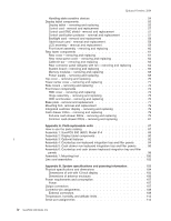
Updated October, 2008 Handling static-sensitive devices 54 Display tablet components 55 Display tablet - removing and replacing 55 Control card - removal and replacement 57 Control card EMC shield - removal and replacement 57 Control card button protector - removal and replacement 57 Backlight card - removal and replacement 58 Tablet touch card - removal and replacement 58 LCD assembly - removal and replacement 59 Front bezel assembly - removing and replacing 60 Rear tower components 61 Rear cover - removing and replacing 61 Rear metal panel cover - removing and replacing 62 Cable-tie bar - removing and replacing 63 Rear connector panel (tailgate) with fan - removing and replacing . . . . . 64 System board - removing and replacing 66 Memory modules - removing and replacing 68 Power supply - removing and replacing 68 Top cover - removing and replacing 70 Tower center cover - removing and replacing 71 Side covers - removing and replacing 72 Front tower components 73 HDD cover - removing and replacing 73 Hinge assembly - removing and replacing 75 HDD and bracket - removing and replacing 76 Base plate - removal and replacement 77 Mounting foot- removal and replacement 79 Integrated customer display - removing and replacing 79 Cash drawer FRUs - removing and replacing 79 Full-size cash drawer FRUs - removing and replacing 79 Common cash-drawer FRUs - removing and replacing 81 Appendix A. Field-replaceable units 87 How to use the parts catalog 87 Assembly 1: SurePOS 500 (4851) Model 514 88 Assembly 2: Display tablet components 90 | Assembly 3: Optional features 92 Assembly 4: Countertop non-keyboard integration tray and filler panels . . . . 94 Assembly 5: Cash drawer non-keyboard integration tray and filler panels . . . 96 Assembly 6: Countertop and cash drawer keyboard integration tray and filler panels 98 Assembly 7: Mounting foot 100 Line cord assemblies 102 Appendix B. System specifications and planning information 103 Physical specifications and dimensions 104 Dimensions of unit with 12-inch display 105 Dimensions of antenna enclosure 106 Power requirements and consumption 107 Power 107 Output connectors 107 Connector-pin assignments 108 External connectors 108 Temperature, humidity, and altitude limits 112 Serial port assignments 112 iv SurePOS 500 Model 514
-
 1
1 -
 2
2 -
 3
3 -
 4
4 -
 5
5 -
 6
6 -
 7
7 -
 8
8 -
 9
9 -
 10
10 -
 11
11 -
 12
12 -
13
-
14
-
15
-
16
-
17
-
18
-
19
-
20
-
21
-
22
-
23
-
24
-
25
-
26
-
27
-
28
-
29
-
30
-
31
-
32
-
33
-
34
-
35
-
36
-
37
-
38
-
39
-
40
-
41
-
42
-
43
-
44
-
45
-
46
-
47
-
48
-
49
-
50
-
51
-
52
-
53
-
54
-
55
-
56
-
57
-
58
-
59
-
60
-
61
-
62
-
63
-
64
-
65
-
66
-
67
-
68
-
69
-
70
-
71
-
72
-
73
-
74
-
75
-
76
-
77
-
78
-
79
-
80
-
81
-
82
-
83
-
84
-
85
-
86
-
87
-
88
-
89
-
90
-
91
-
92
-
93
-
94
-
95
-
96
-
97
-
98
-
99
-
100
-
101
-
102
-
103
-
104
-
105
-
106
-
107
-
108
-
109
-
110
-
111
-
112
-
113
-
114
-
115
-
116
-
117
-
118
-
119
-
120
-
121
-
122
-
123
-
124
-
125
-
126
-
127
-
128
-
129
-
130
-
131
-
132
-
133
-
134
-
135
-
136
-
137
-
138
-
139
-
140
-
141
-
142
-
143
-
144
-
145
-
146
-
147
-
148
-
149
-
150
-
151
-
152
-
153
-
154
-
155
-
156
-
157
-
158
-
159
-
160
-
161
-
162
 |
 |
