Icom IC-80AD Instruction Manual - Page 13
Dkeypad - gps
 |
View all Icom IC-80AD manuals
Add to My Manuals
Save this manual to your list of manuals |
Page 13 highlights
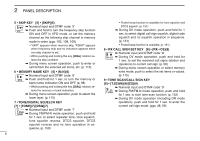
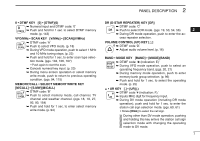
PANEL DESCRIPTION 2 !0 EXTERNAL DC IN JACK [DC IN] ± Connects the supplied wall charger, BC-167SA/SC/SV, to charge the attached battery pack. (p. 12) ± Connect an external DC power supply through the optional CP-12L, CP-19R or OPC-254L for external DC operation. (p. 15) !1 DATA JACK [DATA] (pgs. 74, 77, 158) Connects a PC through the optional data communication cable, OPC-1529R, for low-speed data communication in DV mode or cloning operation. The jack and cable are also used to connect a GPS receiver. D KEYPAD ± Push to input numeral for frequency input, memory channel selection, etc. ± Push to enter or send the DTMF code. (pgs. 143-145) 1 • VOLUME/DIAL KEY [1] • [VD](1) 1 ± Numeral input and DTMF code: '1' ± Push and hold for 1 sec. to exchange the assigned 2 functions between [DIAL] and [ ]/[ ]. (p. 20) 3 2 • TUNING STEP KEY [2] • [TS](2) ± Numeral input and DTMF code: '2' 4 ± Push and hold for 1 sec. to enter tuning step set 5 mode. (p. 22) ± During menu screen operation or select memory 6 write mode, push to select the set items or values. 7 (p. 115) 3 • OUTPUT POWER KEY [3] • [LOW](3) 8 ± Numeral input and DTMF code: '3' 9 ± Push and hold for 1 sec. to select the output power. (p. 27) 10 • Selects the transmit output power from high, mid, low 11 and S-low. • While pushing and holding this key, [DIAL] rotation se- 12 lects the output power. 13 4 • DUPLEX KEY [4] • [DUP](4) ± Numeral input and DTMF code: '4' 14 ± Push and hold for 1 sec. to select minus duplex, 15 plus duplex, and simplex operation. (p. 31) • "DUP-" (minus duplex), "DUP" (plus duplex) and no 16 indication (simplex) appear in order. 17 • While pushing and holding this key, [DIAL] rotation se- lects the duplex operation. 18 ± During menu screen operation, push to select the upper layer. (p. 115) 19 5
-
 1
1 -
2
-
3
-
4
-
5
-
6
-
7
-
 8
8 -
 9
9 -
 10
10 -
 11
11 -
 12
12 -
 13
13 -
 14
14 -
 15
15 -
 16
16 -
 17
17 -
 18
18 -
19
-
20
-
21
-
22
-
23
-
24
-
25
-
26
-
27
-
28
-
29
-
30
-
31
-
32
-
33
-
34
-
35
-
36
-
37
-
38
-
39
-
40
-
41
-
42
-
43
-
44
-
45
-
46
-
47
-
48
-
49
-
50
-
51
-
52
-
53
-
54
-
55
-
56
-
57
-
58
-
59
-
60
-
61
-
62
-
63
-
64
-
65
-
66
-
67
-
68
-
69
-
70
-
71
-
72
-
73
-
74
-
75
-
76
-
77
-
78
-
79
-
80
-
81
-
82
-
83
-
84
-
85
-
86
-
87
-
88
-
89
-
90
-
91
-
92
-
93
-
94
-
95
-
96
-
97
-
98
-
99
-
100
-
101
-
102
-
103
-
104
-
105
-
106
-
107
-
108
-
109
-
110
-
111
-
112
-
113
-
114
-
115
-
116
-
117
-
118
-
119
-
120
-
121
-
122
-
123
-
124
-
125
-
126
-
127
-
128
-
129
-
130
-
131
-
132
-
133
-
134
-
135
-
136
-
137
-
138
-
139
-
140
-
141
-
142
-
143
-
144
-
145
-
146
-
147
-
148
-
149
-
150
-
151
-
152
-
153
-
154
-
155
-
156
-
157
-
158
-
159
-
160
-
161
-
162
-
163
-
164
-
165
-
166
-
167
-
168
-
169
-
170
-
171
-
172
-
173
-
174
-
175
-
176
-
177
-
178
-
179
-
180
-
181
-
182
-
183
-
184
-
185
-
186
-
187
-
188
 |
 |
