Lenovo ThinkServer RD210 Hardware Maintenance Manual - Page 139
Connecting the cables, Rack Installation Instructions
 |
View all Lenovo ThinkServer RD210 manuals
Add to My Manuals
Save this manual to your list of manuals |
Page 139 highlights
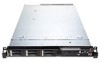
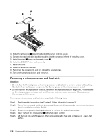
1. If you removed any air baffles, reinstall them now (see "Removing and installing the DIMM air baffle" on page 77). 2. If you removed the cover, replace it (see "Removing and replacing the cover" on page 72). 3. Install the server in the rack cabinet (see the Rack Installation Instructions that come with the server for instructions). 4. Reconnect the cables and power cords. 5. Update the server configuration (see "Updating the server configuration" on page 132). 6. Slide the server back into the rack, if necessary. Connecting the cables The following illustration shows the locations of the input and output connectors on the front of the server. 00000000000000 00 000 00 000 000 000 1 Hard disk drive activity LED (green) 2 Hard disk drive status LED (amber) 3 Drive bay 0 4 Drive bay 2 5 Drive bay 4 6 Power-control button and LED 7 Operator information panel 8 Operator information panel release latch 9 Video connector 10 USB 1 connector 11 Rack release latch 12 USB 2 connector 13 Optical drive eject button 14 Optical drive activity LED 15 Optical drive bay 16 Drive bay 5 17 Drive bay 3 18 Drive bay 1 19 Rack release latch The following illustration shows the LEDs on the rear of the server. 00000000 00000 000 000 0000 000 000 000 00000000 0000000 000 0000000 0000000 1 Slot 1, PCI Express 2 Ethernet activity LED 3 Ethernet link LED 4 Video connector 5 Slot 2, PCI Express 11 USB 3 connector 12 Serial connector 13 System-error LED (amber) 14 System-locator LED (blue) 15 Power-control button LED (green) Chapter 7. Installing optional devices and replacing customer replaceable units 131
-
 1
1 -
2
-
3
-
4
-
5
-
6
-
7
-
8
-
9
-
10
-
11
-
12
-
13
-
14
-
15
-
16
-
17
-
18
-
19
-
20
-
21
-
22
-
23
-
24
-
25
-
26
-
27
-
28
-
29
-
30
-
31
-
32
-
33
-
34
-
35
-
36
-
37
-
38
-
39
-
40
-
41
-
42
-
43
-
44
-
45
-
46
-
47
-
48
-
49
-
50
-
51
-
52
-
53
-
54
-
55
-
56
-
57
-
58
-
59
-
60
-
61
-
62
-
63
-
64
-
65
-
66
-
67
-
68
-
69
-
70
-
71
-
72
-
73
-
74
-
75
-
76
-
77
-
78
-
79
-
80
-
81
-
82
-
83
-
84
-
85
-
86
-
87
-
88
-
89
-
90
-
91
-
92
-
93
-
94
-
95
-
96
-
97
-
98
-
99
-
100
-
101
-
102
-
103
-
104
-
105
-
106
-
107
-
108
-
109
-
110
-
111
-
112
-
113
-
114
-
115
-
116
-
117
-
118
-
119
-
120
-
121
-
122
-
123
-
124
-
125
-
126
-
127
-
128
-
129
-
130
-
131
-
132
-
133
-
 134
134 -
 135
135 -
 136
136 -
 137
137 -
 138
138 -
 139
139 -
 140
140 -
 141
141 -
 142
142 -
 143
143 -
 144
144 -
145
-
146
-
147
-
148
-
149
-
150
-
151
-
152
-
153
-
154
-
155
-
156
-
157
-
158
-
159
-
160
-
161
-
162
-
163
-
164
-
165
-
166
-
167
-
168
-
169
-
170
-
171
-
172
-
173
-
174
-
175
-
176
-
177
-
178
-
179
-
180
-
181
-
182
 |
 |
