Lenovo ThinkServer RD210 Hardware Maintenance Manual - Page 77
System-board internal connectors, Handle the device carefully, holding it by its edges or its frame.
 |
View all Lenovo ThinkServer RD210 manuals
Add to My Manuals
Save this manual to your list of manuals |
Page 77 highlights
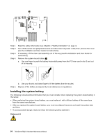
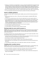
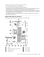
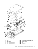
• Handle the device carefully, holding it by its edges or its frame. • Do not touch solder joints, pins, or exposed circuitry. • Do not leave the device where others can handle and damage it. • While the device is still in its static-protective package, touch it to an unpainted metal part of the server for at least 2 seconds. This drains static electricity from the package and from your body. • Remove the device from its package and install it directly into the server without setting down the device. If it is necessary to set down the device, put it back into its static-protective package. Do not place the device on the server cover or on a metal surface. • Take additional care when you handle devices during cold weather. Heating reduces indoor humidity and increases static electricity. System-board internal connectors The following illustration shows the internal connectors on the system board. 1 Battery 2 Optional two-port Ethernet card connector 3 PCI riser connector 4 DIMM connectors 13 Fan 4 connector 14 Fan 5 connector 15 Fan 6 connector 16 Fan 4 connector Chapter 7. Installing optional devices and replacing customer replaceable units 69
-
 1
1 -
2
-
3
-
4
-
5
-
6
-
7
-
8
-
9
-
10
-
11
-
12
-
13
-
14
-
15
-
16
-
17
-
18
-
19
-
20
-
21
-
22
-
23
-
24
-
25
-
26
-
27
-
28
-
29
-
30
-
31
-
32
-
33
-
34
-
35
-
36
-
37
-
38
-
39
-
40
-
41
-
42
-
43
-
44
-
45
-
46
-
47
-
48
-
49
-
50
-
51
-
52
-
53
-
54
-
55
-
56
-
57
-
58
-
59
-
60
-
61
-
62
-
63
-
64
-
65
-
66
-
67
-
68
-
69
-
70
-
71
-
 72
72 -
 73
73 -
 74
74 -
 75
75 -
 76
76 -
 77
77 -
 78
78 -
 79
79 -
 80
80 -
 81
81 -
 82
82 -
83
-
84
-
85
-
86
-
87
-
88
-
89
-
90
-
91
-
92
-
93
-
94
-
95
-
96
-
97
-
98
-
99
-
100
-
101
-
102
-
103
-
104
-
105
-
106
-
107
-
108
-
109
-
110
-
111
-
112
-
113
-
114
-
115
-
116
-
117
-
118
-
119
-
120
-
121
-
122
-
123
-
124
-
125
-
126
-
127
-
128
-
129
-
130
-
131
-
132
-
133
-
134
-
135
-
136
-
137
-
138
-
139
-
140
-
141
-
142
-
143
-
144
-
145
-
146
-
147
-
148
-
149
-
150
-
151
-
152
-
153
-
154
-
155
-
156
-
157
-
158
-
159
-
160
-
161
-
162
-
163
-
164
-
165
-
166
-
167
-
168
-
169
-
170
-
171
-
172
-
173
-
174
-
175
-
176
-
177
-
178
-
179
-
180
-
181
-
182
 |
 |
