Lenovo ThinkServer RD210 Hardware Maintenance Manual - Page 143
Removing and installing FRUs, Removing the 240 VA safety cover
 |
View all Lenovo ThinkServer RD210 manuals
Add to My Manuals
Save this manual to your list of manuals |
Page 143 highlights
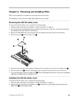
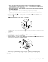
Chapter 8. Removing and installing FRUs FRUs must be replaced or installed only by trained service technicians. The illustrations in this document might differ slightly from your model. Removing the 240 VA safety cover To remove the 240 VA safety cover, complete the following steps: 1. Read the safety information (see Chapter 2 "Safety information" on page 3). 2. Turn off the server and peripheral devices and disconnect all power cords; then, remove the cover (see the Installation and User Guide for instructions). 3. Remove the SAS/SATA riser-card assembly (see the Installation and User Guide for instructions). 4. Remove the screw 3 from the safety cover 2 . 5. Disconnect the hard disk drive backplane cables from the connector on the front of the safety cover 2 . 6. Slide the safety cover 2 forward to disengage it from the system board, then lift it out of the server. 7. If you are instructed to return the safety cover 2 , follow all packaging instructions, and use any packaging materials for shipping that are supplied to you. Installing the 240 VA safety cover To install the 240 VA safety cover, complete the following steps: 1. Read the safety information (see Chapter 2 "Safety information" on page 3). 2. Align the tabs on the bottom of the safety cover 2 with the slots on the system board and lower the safety cover 2 into the system board. © Copyright Lenovo 2005, 2010 135
-
 1
1 -
2
-
3
-
4
-
5
-
6
-
7
-
8
-
9
-
10
-
11
-
12
-
13
-
14
-
15
-
16
-
17
-
18
-
19
-
20
-
21
-
22
-
23
-
24
-
25
-
26
-
27
-
28
-
29
-
30
-
31
-
32
-
33
-
34
-
35
-
36
-
37
-
38
-
39
-
40
-
41
-
42
-
43
-
44
-
45
-
46
-
47
-
48
-
49
-
50
-
51
-
52
-
53
-
54
-
55
-
56
-
57
-
58
-
59
-
60
-
61
-
62
-
63
-
64
-
65
-
66
-
67
-
68
-
69
-
70
-
71
-
72
-
73
-
74
-
75
-
76
-
77
-
78
-
79
-
80
-
81
-
82
-
83
-
84
-
85
-
86
-
87
-
88
-
89
-
90
-
91
-
92
-
93
-
94
-
95
-
96
-
97
-
98
-
99
-
100
-
101
-
102
-
103
-
104
-
105
-
106
-
107
-
108
-
109
-
110
-
111
-
112
-
113
-
114
-
115
-
116
-
117
-
118
-
119
-
120
-
121
-
122
-
123
-
124
-
125
-
126
-
127
-
128
-
129
-
130
-
131
-
132
-
133
-
134
-
135
-
136
-
137
-
 138
138 -
 139
139 -
 140
140 -
 141
141 -
 142
142 -
 143
143 -
 144
144 -
 145
145 -
 146
146 -
 147
147 -
 148
148 -
149
-
150
-
151
-
152
-
153
-
154
-
155
-
156
-
157
-
158
-
159
-
160
-
161
-
162
-
163
-
164
-
165
-
166
-
167
-
168
-
169
-
170
-
171
-
172
-
173
-
174
-
175
-
176
-
177
-
178
-
179
-
180
-
181
-
182
 |
 |
