Lenovo ThinkServer RD210 Hardware Maintenance Manual - Page 83
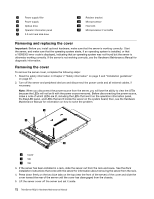
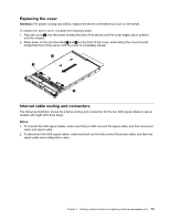
under the cable retention tab and the top cover latch receptacle.
 |
View all Lenovo ThinkServer RD210 manuals
Add to My Manuals
Save this manual to your list of manuals |
Page 83 highlights
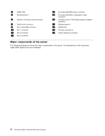
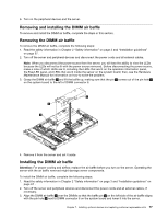
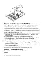
Table 5. 1 2 Top cover latch receptacle Operator panel cable The following illustration shows the internal routing and connector for the USB/video cable. Note: The USB cable is routed under the video cable and then both the USB and video cables are routed under the cable retention tab and the top cover latch receptacle. Table 6. 1 2 Top cover latch receptacle Cable retention tab Chapter 7. Installing optional devices and replacing customer replaceable units 75
-
 1
1 -
2
-
3
-
4
-
5
-
6
-
7
-
8
-
9
-
10
-
11
-
12
-
13
-
14
-
15
-
16
-
17
-
18
-
19
-
20
-
21
-
22
-
23
-
24
-
25
-
26
-
27
-
28
-
29
-
30
-
31
-
32
-
33
-
34
-
35
-
36
-
37
-
38
-
39
-
40
-
41
-
42
-
43
-
44
-
45
-
46
-
47
-
48
-
49
-
50
-
51
-
52
-
53
-
54
-
55
-
56
-
57
-
58
-
59
-
60
-
61
-
62
-
63
-
64
-
65
-
66
-
67
-
68
-
69
-
70
-
71
-
72
-
73
-
74
-
75
-
76
-
77
-
 78
78 -
 79
79 -
 80
80 -
 81
81 -
 82
82 -
 83
83 -
 84
84 -
 85
85 -
 86
86 -
 87
87 -
 88
88 -
89
-
90
-
91
-
92
-
93
-
94
-
95
-
96
-
97
-
98
-
99
-
100
-
101
-
102
-
103
-
104
-
105
-
106
-
107
-
108
-
109
-
110
-
111
-
112
-
113
-
114
-
115
-
116
-
117
-
118
-
119
-
120
-
121
-
122
-
123
-
124
-
125
-
126
-
127
-
128
-
129
-
130
-
131
-
132
-
133
-
134
-
135
-
136
-
137
-
138
-
139
-
140
-
141
-
142
-
143
-
144
-
145
-
146
-
147
-
148
-
149
-
150
-
151
-
152
-
153
-
154
-
155
-
156
-
157
-
158
-
159
-
160
-
161
-
162
-
163
-
164
-
165
-
166
-
167
-
168
-
169
-
170
-
171
-
172
-
173
-
174
-
175
-
176
-
177
-
178
-
179
-
180
-
181
-
182
 |
 |

Table 5.
1
Top cover latch receptacle
2
Operator panel cable
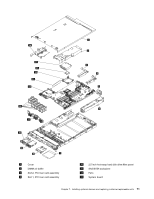
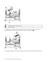
The following illustration shows the internal routing and connector for the USB/video cable.
Note:
The USB cable is routed under the video cable and then both the USB and video cables are routed
under the cable retention tab and the top cover latch receptacle.
Table 6.
1
Top cover latch receptacle
2
Cable retention tab
Chapter 7
.
Installing optional devices and replacing customer replaceable units
75