Lexmark X500n Service Manual - Page 178
System board cage removal, Left front cover removal
 |
View all Lexmark X500n manuals
Add to My Manuals
Save this manual to your list of manuals |
Page 178 highlights
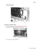
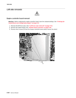
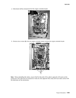
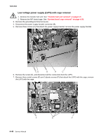
7100-XXX System board cage removal 1. Remove the left front cover. See "Left front cover removal" on page 4-15. 2. Remove the three screws (A) securing the engine card shield. 3. Remove the engine card shield. 4. Disconnect all the cables from the engine card. 5. Disconnect the modem speaker cable from the RIP card. 6. Remove the three screws (B) which secure the card cage to the printer frame. 7. Carefully remove the card cage from the printer. Note: The engine controller board and system / RIP board do not need to be removed to perform this removal. 4-38 Service Manual
-
 1
1 -
2
-
3
-
4
-
5
-
6
-
7
-
8
-
9
-
10
-
11
-
12
-
13
-
14
-
15
-
16
-
17
-
18
-
19
-
20
-
21
-
22
-
23
-
24
-
25
-
26
-
27
-
28
-
29
-
30
-
31
-
32
-
33
-
34
-
35
-
36
-
37
-
38
-
39
-
40
-
41
-
42
-
43
-
44
-
45
-
46
-
47
-
48
-
49
-
50
-
51
-
52
-
53
-
54
-
55
-
56
-
57
-
58
-
59
-
60
-
61
-
62
-
63
-
64
-
65
-
66
-
67
-
68
-
69
-
70
-
71
-
72
-
73
-
74
-
75
-
76
-
77
-
78
-
79
-
80
-
81
-
82
-
83
-
84
-
85
-
86
-
87
-
88
-
89
-
90
-
91
-
92
-
93
-
94
-
95
-
96
-
97
-
98
-
99
-
100
-
101
-
102
-
103
-
104
-
105
-
106
-
107
-
108
-
109
-
110
-
111
-
112
-
113
-
114
-
115
-
116
-
117
-
118
-
119
-
120
-
121
-
122
-
123
-
124
-
125
-
126
-
127
-
128
-
129
-
130
-
131
-
132
-
133
-
134
-
135
-
136
-
137
-
138
-
139
-
140
-
141
-
142
-
143
-
144
-
145
-
146
-
147
-
148
-
149
-
150
-
151
-
152
-
153
-
154
-
155
-
156
-
157
-
158
-
159
-
160
-
161
-
162
-
163
-
164
-
165
-
166
-
167
-
168
-
169
-
170
-
171
-
172
-
 173
173 -
 174
174 -
 175
175 -
 176
176 -
 177
177 -
 178
178 -
 179
179 -
 180
180 -
 181
181 -
 182
182 -
 183
183 -
184
-
185
-
186
-
187
-
188
-
189
-
190
-
191
-
192
-
193
-
194
-
195
-
196
-
197
-
198
-
199
-
200
-
201
-
202
-
203
-
204
-
205
-
206
-
207
-
208
-
209
-
210
-
211
-
212
-
213
-
214
-
215
-
216
-
217
-
218
-
219
-
220
-
221
-
222
-
223
-
224
-
225
-
226
-
227
-
228
-
229
-
230
-
231
-
232
-
233
-
234
-
235
-
236
-
237
-
238
-
239
-
240
-
241
-
242
-
243
-
244
 |
 |

4-38
Service Manual
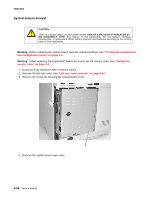
7100-XXX
System board cage removal
1.
Remove the left front cover. See
“Left front cover removal” on page 4-15
.
2.
Remove the three screws (A) securing the engine card shield.
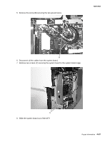
3.
Remove the engine card shield.
4.
Disconnect all the cables from the engine card.
5.
Disconnect the modem speaker cable from the RIP card.
6.
Remove the three screws (B) which secure the card cage to the printer frame.
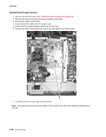
7.
Carefully remove the card cage from the printer.
Note:
The engine controller board and system / RIP board do not need to be removed to perform this
removal.