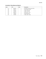
Lexmark X500n Service Manual - Page 239
Index, i-xviii
 |
View all Lexmark X500n manuals
Add to My Manuals
Save this manual to your list of manuals |
Page 239 highlights
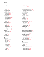
Index A Accessing jam areas 3-23 acronyms 1-17 ADF mechanism cover removal 4-55 ADF paper jams 3-30 ADF unit removal 4-53 B bracket assembly removal 4-30 C cleaning roller clutch removal 4-25 cleaning roller cover removal 4-4 clearances 1-4 clutch removal 4-27 copy specifications 1-11 CRU/FRU and supplies removals 4-4 D developer drive assembly removal 4-22 diagnostic aids 3-1 diagnostic information printer service checks 2-14 service error codes 2-3 symptom tables 2-11 user attendance messages 2-8 user status messages 2-6 E emulations 1-6 engine controller board removal 4-34 wiring diagram 5-9 engine controller board connections 5-10 environment 1-5 erase lamp removal 4-20 error codes service 2-3 user attendance messages 2-8 user status messages 2-6 ESD-sensitive parts 4-2 F fax specifications 1-11 document sizes supported 1-12 miscellaneous 1-12 phone network connectivity 1-11 7100-XXX scan resolutions 1-12 flatbed assembly removal 4-49 front cover assembly removal 4-12 front door interlock switch removal 4-21 fuser aseembly removal 4-6 fuser fan assembly removal 4-43 H handling ESD-sensitive parts 4-2 high voltage power supply removal 4-39 HVPS cage removal 4-41 J jam messages JAM-A tray, rear (tray 1) 3-24 JAM-A tray, rear (tray 2) 3-26 JAM-B rear 3-27 JAM-C rear 3-29 L Laser unit assembly removal 4-18 left front cover removal 4-15 left rear cover removal 4-16 left tray guide assembly removal 4-42 Lithium Information i-xviii Lithium Warning i-xviii locations 5-1 circuit boards 5-5 connections engine card 5-10 modem card 5-18 engine controller board 5-16 fans and motors 5-6 high voltage supply board 5-17 low voltage power supply board 5-16 printer front and rear view 5-1 RIP board 5-15 scanner 5-3 sensors printer engine 5-4 solenoids and clutches 5-7 wiring diagram engine controller board 5-9 Index I-1
-
 1
1 -
2
-
3
-
4
-
5
-
6
-
7
-
8
-
9
-
10
-
11
-
12
-
13
-
14
-
15
-
16
-
17
-
18
-
19
-
20
-
21
-
22
-
23
-
24
-
25
-
26
-
27
-
28
-
29
-
30
-
31
-
32
-
33
-
34
-
35
-
36
-
37
-
38
-
39
-
40
-
41
-
42
-
43
-
44
-
45
-
46
-
47
-
48
-
49
-
50
-
51
-
52
-
53
-
54
-
55
-
56
-
57
-
58
-
59
-
60
-
61
-
62
-
63
-
64
-
65
-
66
-
67
-
68
-
69
-
70
-
71
-
72
-
73
-
74
-
75
-
76
-
77
-
78
-
79
-
80
-
81
-
82
-
83
-
84
-
85
-
86
-
87
-
88
-
89
-
90
-
91
-
92
-
93
-
94
-
95
-
96
-
97
-
98
-
99
-
100
-
101
-
102
-
103
-
104
-
105
-
106
-
107
-
108
-
109
-
110
-
111
-
112
-
113
-
114
-
115
-
116
-
117
-
118
-
119
-
120
-
121
-
122
-
123
-
124
-
125
-
126
-
127
-
128
-
129
-
130
-
131
-
132
-
133
-
134
-
135
-
136
-
137
-
138
-
139
-
140
-
141
-
142
-
143
-
144
-
145
-
146
-
147
-
148
-
149
-
150
-
151
-
152
-
153
-
154
-
155
-
156
-
157
-
158
-
159
-
160
-
161
-
162
-
163
-
164
-
165
-
166
-
167
-
168
-
169
-
170
-
171
-
172
-
173
-
174
-
175
-
176
-
177
-
178
-
179
-
180
-
181
-
182
-
183
-
184
-
185
-
186
-
187
-
188
-
189
-
190
-
191
-
192
-
193
-
194
-
195
-
196
-
197
-
198
-
199
-
200
-
201
-
202
-
203
-
204
-
205
-
206
-
207
-
208
-
209
-
210
-
211
-
212
-
213
-
214
-
215
-
216
-
217
-
218
-
219
-
220
-
221
-
222
-
223
-
224
-
225
-
226
-
227
-
228
-
229
-
230
-
231
-
232
-
233
-
 234
234 -
 235
235 -
 236
236 -
 237
237 -
 238
238 -
 239
239 -
 240
240 -
 241
241 -
 242
242 -
 243
243 -
 244
244
 |
 |
