Lexmark X500n Service Manual - Page 73
Cover open service check
 |
View all Lexmark X500n manuals
Add to My Manuals
Save this manual to your list of manuals |
Page 73 highlights
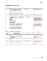
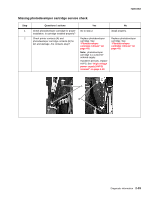
7100-XXX Cover open service check Step 1 2 3 4 5 Questions / actions Yes Turn printer off, and remove right cover. See "Right cover removal" on page 4-13. Check all interlock switch (top, rear and front) actuators for proper operation. Are actuators good? Go to step 2. Check each interlock switch (top, rear and front) for proper operation and damage. Listen for switching action. Using an ohmmeter, check switches. When switch is open (cover open), resistance between pin 1 and pin 3 is 0 and pin 1 and 2 is infinite. Closing switch will show 0 resistance between pins 1 and 2 and infinite resistance between pins 1 and 3. Are switches good? Turn printer on. Check for 5 VDC between front cover interlock switch pin 1 (top pin) and ground. Is 5 VDC present? Turn printer off, and check cable for continuity between LVPS ACN2 pin 1 and cable that connects to front cover interlock switch pin 1. Is cable okay? Check the following cables for continuity: • Engine controller board MCN4 pin 1 to rear interlock switch pin 3 • Engine controller board MCN4 pin 3 to top interlock switch pin 3 • Top cover interlock switch pin 1 to front cover interlock switch pin 2 • Top cover interlock switch pin 2 to rear cover interlock switch pin 1 • LVPS ACN2 pin 2 to rear cover interlock switch pin 2. Are any cables defective? Go to step 3. Go to step 5. Replace LVPS. See "Low voltage power supply (LVPS) with cage removal" on page 4-40. Replace cable. No Replace appropriate actuator: Front cover for front cover interlock switch. See "Front cover assembly removal" on page 4-12. Top cover assembly for top cover interlock switch. See "Top cover assembly removal" on page 4-10. Rear cover actuator for rear cover interlock switch. Actuator is contained in parts packet. Replace switch in question. See "Front door interlock switch with bracket" on page 4-21 for front interlock switch, see "Power supply fan removal" on page 4-48 for rear and top interlock switches. Go to step 4. Replace cable. Replace engine controller board. See "Engine controller board removal" on page 4-34. Diagnostic information 2-35
-
 1
1 -
2
-
3
-
4
-
5
-
6
-
7
-
8
-
9
-
10
-
11
-
12
-
13
-
14
-
15
-
16
-
17
-
18
-
19
-
20
-
21
-
22
-
23
-
24
-
25
-
26
-
27
-
28
-
29
-
30
-
31
-
32
-
33
-
34
-
35
-
36
-
37
-
38
-
39
-
40
-
41
-
42
-
43
-
44
-
45
-
46
-
47
-
48
-
49
-
50
-
51
-
52
-
53
-
54
-
55
-
56
-
57
-
58
-
59
-
60
-
61
-
62
-
63
-
64
-
65
-
66
-
67
-
 68
68 -
 69
69 -
 70
70 -
 71
71 -
 72
72 -
 73
73 -
 74
74 -
 75
75 -
 76
76 -
 77
77 -
 78
78 -
79
-
80
-
81
-
82
-
83
-
84
-
85
-
86
-
87
-
88
-
89
-
90
-
91
-
92
-
93
-
94
-
95
-
96
-
97
-
98
-
99
-
100
-
101
-
102
-
103
-
104
-
105
-
106
-
107
-
108
-
109
-
110
-
111
-
112
-
113
-
114
-
115
-
116
-
117
-
118
-
119
-
120
-
121
-
122
-
123
-
124
-
125
-
126
-
127
-
128
-
129
-
130
-
131
-
132
-
133
-
134
-
135
-
136
-
137
-
138
-
139
-
140
-
141
-
142
-
143
-
144
-
145
-
146
-
147
-
148
-
149
-
150
-
151
-
152
-
153
-
154
-
155
-
156
-
157
-
158
-
159
-
160
-
161
-
162
-
163
-
164
-
165
-
166
-
167
-
168
-
169
-
170
-
171
-
172
-
173
-
174
-
175
-
176
-
177
-
178
-
179
-
180
-
181
-
182
-
183
-
184
-
185
-
186
-
187
-
188
-
189
-
190
-
191
-
192
-
193
-
194
-
195
-
196
-
197
-
198
-
199
-
200
-
201
-
202
-
203
-
204
-
205
-
206
-
207
-
208
-
209
-
210
-
211
-
212
-
213
-
214
-
215
-
216
-
217
-
218
-
219
-
220
-
221
-
222
-
223
-
224
-
225
-
226
-
227
-
228
-
229
-
230
-
231
-
232
-
233
-
234
-
235
-
236
-
237
-
238
-
239
-
240
-
241
-
242
-
243
-
244
 |
 |
