Lexmark X500n Service Manual - Page 75
Paper size sensing service check
 |
View all Lexmark X500n manuals
Add to My Manuals
Save this manual to your list of manuals |
Page 75 highlights
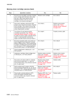
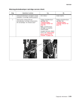
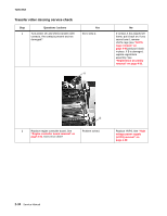
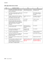
7100-XXX Paper size sensing service check Step 1 2 3 4 5 Questions / actions Yes No Turn printer off, and remove engine controller board shield. See "Engine controller board removal" on page 4-34 for steps to remove engine controller board shield. Is cable properly connected to engine controller board connector MCN7? Turn printer on, and check for 5 VDC between MCN7 pin 2 and ground. Is 5 VDC present? Check for cable continuity between LVPS ACN1 and engine controller board POCN. Is continuity present? If paper tray is removed, set paper tray for desired paper size, and insert paper tray into printer. Using table below, check for proper paper size sensor action by taking voltage readings between ground and engine controller board MCN7 pins 4, 6, 8 and 10. Is paper size sensor working properly? Check cable for continuity between engine board MCN7 and paper size sensor. Also check for shorted pins. Is cable okay? Go to step 2. Go to step 4. Replace LVPS. See "Low voltage power supply (LVPS) with cage removal" on page 4-40. Replace engine controller board. See "Engine controller board removal" on page 4-34. Replace paper size sensor. See "Left tray guide assembly removal" on page 4-42. Properly connect cable. Go to step 3. Go to step 4. Go to step 5. Replace cable by replacing the left tray guide assembly. See "Left tray guide assembly removal" on page 4-42. Paper tray setting Standard tray A4 Letter EXE B5J B51 #10 DL Legal tray MCN7 (all voltages measured from pin to ground) pin 4 5 VDC 5 VDC 0 VDC 5 VDC 5 VDC 0 VDC 0 VDC 0 VDC pin 6 5 VDC 0 VDC 5 VDC 0 VDC 0 VDC 0 VDC 0 VDC 0 VDC pin 8 0 VDC 5 VDC 0 VDC 0 VDC 0 VDC 0 VDC 0 VDC 5 VDC pin 10 5 VDC 5 VDC 5 VDC 5 VDC 5 VDC 5 VDC 5 VDC 5 VDC Diagnostic information 2-37
-
 1
1 -
2
-
3
-
4
-
5
-
6
-
7
-
8
-
9
-
10
-
11
-
12
-
13
-
14
-
15
-
16
-
17
-
18
-
19
-
20
-
21
-
22
-
23
-
24
-
25
-
26
-
27
-
28
-
29
-
30
-
31
-
32
-
33
-
34
-
35
-
36
-
37
-
38
-
39
-
40
-
41
-
42
-
43
-
44
-
45
-
46
-
47
-
48
-
49
-
50
-
51
-
52
-
53
-
54
-
55
-
56
-
57
-
58
-
59
-
60
-
61
-
62
-
63
-
64
-
65
-
66
-
67
-
68
-
69
-
 70
70 -
 71
71 -
 72
72 -
 73
73 -
 74
74 -
 75
75 -
 76
76 -
 77
77 -
 78
78 -
 79
79 -
 80
80 -
81
-
82
-
83
-
84
-
85
-
86
-
87
-
88
-
89
-
90
-
91
-
92
-
93
-
94
-
95
-
96
-
97
-
98
-
99
-
100
-
101
-
102
-
103
-
104
-
105
-
106
-
107
-
108
-
109
-
110
-
111
-
112
-
113
-
114
-
115
-
116
-
117
-
118
-
119
-
120
-
121
-
122
-
123
-
124
-
125
-
126
-
127
-
128
-
129
-
130
-
131
-
132
-
133
-
134
-
135
-
136
-
137
-
138
-
139
-
140
-
141
-
142
-
143
-
144
-
145
-
146
-
147
-
148
-
149
-
150
-
151
-
152
-
153
-
154
-
155
-
156
-
157
-
158
-
159
-
160
-
161
-
162
-
163
-
164
-
165
-
166
-
167
-
168
-
169
-
170
-
171
-
172
-
173
-
174
-
175
-
176
-
177
-
178
-
179
-
180
-
181
-
182
-
183
-
184
-
185
-
186
-
187
-
188
-
189
-
190
-
191
-
192
-
193
-
194
-
195
-
196
-
197
-
198
-
199
-
200
-
201
-
202
-
203
-
204
-
205
-
206
-
207
-
208
-
209
-
210
-
211
-
212
-
213
-
214
-
215
-
216
-
217
-
218
-
219
-
220
-
221
-
222
-
223
-
224
-
225
-
226
-
227
-
228
-
229
-
230
-
231
-
232
-
233
-
234
-
235
-
236
-
237
-
238
-
239
-
240
-
241
-
242
-
243
-
244
 |
 |
