Lexmark X500n Service Manual - Page 53
Engine, controller board removal, on System board, cage removal on,
 |
View all Lexmark X500n manuals
Add to My Manuals
Save this manual to your list of manuals |
Page 53 highlights
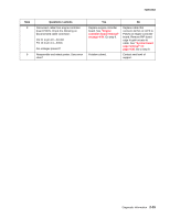
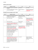
7100-XXX Step 8 9 Questions / actions Disconnect cable from engine controller board POCN. Check the following on disconnected cable connector: Pin 21 to pin 22-24VDC Pin 13 to pin 14-5VDC Are voltages present? Reassemble and retest printer. Does error clear? Yes No Replace engine controller board. See "Engine controller board removal" on page 4-34. Go step 9. Problem solved. Replace cable that connects ACN1 on LVPS to POCN on engine controller board. Remove RIP board cage to gain access to cable. See "System board cage removal" on page 4-38. Go to step 9. Contact next level of support. Diagnostic information 2-15
-
 1
1 -
2
-
3
-
4
-
5
-
6
-
7
-
8
-
9
-
10
-
11
-
12
-
13
-
14
-
15
-
16
-
17
-
18
-
19
-
20
-
21
-
22
-
23
-
24
-
25
-
26
-
27
-
28
-
29
-
30
-
31
-
32
-
33
-
34
-
35
-
36
-
37
-
38
-
39
-
40
-
41
-
42
-
43
-
44
-
45
-
46
-
47
-
 48
48 -
 49
49 -
 50
50 -
 51
51 -
 52
52 -
 53
53 -
 54
54 -
 55
55 -
 56
56 -
 57
57 -
 58
58 -
59
-
60
-
61
-
62
-
63
-
64
-
65
-
66
-
67
-
68
-
69
-
70
-
71
-
72
-
73
-
74
-
75
-
76
-
77
-
78
-
79
-
80
-
81
-
82
-
83
-
84
-
85
-
86
-
87
-
88
-
89
-
90
-
91
-
92
-
93
-
94
-
95
-
96
-
97
-
98
-
99
-
100
-
101
-
102
-
103
-
104
-
105
-
106
-
107
-
108
-
109
-
110
-
111
-
112
-
113
-
114
-
115
-
116
-
117
-
118
-
119
-
120
-
121
-
122
-
123
-
124
-
125
-
126
-
127
-
128
-
129
-
130
-
131
-
132
-
133
-
134
-
135
-
136
-
137
-
138
-
139
-
140
-
141
-
142
-
143
-
144
-
145
-
146
-
147
-
148
-
149
-
150
-
151
-
152
-
153
-
154
-
155
-
156
-
157
-
158
-
159
-
160
-
161
-
162
-
163
-
164
-
165
-
166
-
167
-
168
-
169
-
170
-
171
-
172
-
173
-
174
-
175
-
176
-
177
-
178
-
179
-
180
-
181
-
182
-
183
-
184
-
185
-
186
-
187
-
188
-
189
-
190
-
191
-
192
-
193
-
194
-
195
-
196
-
197
-
198
-
199
-
200
-
201
-
202
-
203
-
204
-
205
-
206
-
207
-
208
-
209
-
210
-
211
-
212
-
213
-
214
-
215
-
216
-
217
-
218
-
219
-
220
-
221
-
222
-
223
-
224
-
225
-
226
-
227
-
228
-
229
-
230
-
231
-
232
-
233
-
234
-
235
-
236
-
237
-
238
-
239
-
240
-
241
-
242
-
243
-
244
 |
 |

Diagnostic information
2-15
7100-XXX
8
Disconnect cable from engine controller
board POCN. Check the following on
disconnected cable connector:
Pin 21 to pin 22—24VDC
Pin 13 to pin 14—5VDC
Are voltages present?
Replace engine controller
board. See
“Engine
controller board removal”
on page 4-34
. Go step 9.
Replace cable that
connects ACN1 on LVPS to
POCN on engine controller
board. Remove RIP board
cage to gain access to
cable. See
“System board
cage removal” on
page 4-38
. Go to step 9.
9
Reassemble and retest printer. Does error
clear?
Problem solved.
Contact next level of
support.
Step
Questions / actions
Yes
No