Lexmark X500n Service Manual - Page 42
Error code, Action, P feed Clutch Tray 1 - fan
 |
View all Lexmark X500n manuals
Add to My Manuals
Save this manual to your list of manuals |
Page 42 highlights
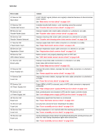
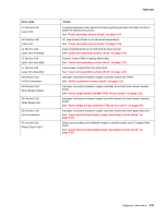
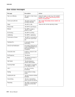
7100-XXX Error code E2 Service Call Main Motor E3 Service Call Transfer Belt Sensor E5 Service Call Transfer Roller Clutch E6 Service Call Transfer Cleaner Solenoid E7 Service Call P feed Clutch Tray 1 E8 Service Call Registration Clutch E9 Service Call OPC Marker Sensor EL Service Call Erase Lamp F0 Service Call Power Supply Fan F4 Service Call Fuser Fan F5 Service Call HV Power Supply Unit F6 Service Call LV Power Supply Unit H0 Service Call Fuser Unit H1 Service Call Fuser Unit H2 Service Call Fuser Unit H3 Service Call Fuser Unit Action A NOT READY signal (rotation error signal) is detected because of abnormal main motor rotation. See "Main motor service check" on page 2-14. Unstable transfer belt rotation-color matching cannot be secured. See "Transfer belt unit service check" on page 2-17. Improper transfer roller clutch cable connection or a shorted or cut cable. See "Transfer roller clutch service check" on page 2-18. Improper cleaning roller clutch cable connection or a shorted or cut cable. See "Transfer belt cleaning roller clutch service check" on page 2-18. Improper paper-feed clutch cable connection or a shorted or cut cable. See "Paper feed clutch service check" on page 2-19. Improper registration clutch cable connection or a shorted or cut cable. See "Registration clutch service check" on page 2-19. Marker sensor is not properly detecting mark on OPC belt. See "OPC belt marker sensor service check" on page 2-20. Improper erase lamp cable connection or a shorted or cut cable. Erase lamp LED terminal may be cut. See "Erase lamp service check" on page 2-21. Improper fan motor rotation, improper fan motor cable connection or a shorted or cut cable. See "Power supply fan service check" on page 2-22. Improper fan motor rotation, improper fan motor cable connection or a shorted or cut cable. See "Fuser fan service check" on page 2-22. Output (BRV) of HVPS is shorted, and or HVPS cable connector is improperly connected. See "High voltage power supply (HVPS) service check" on page 2-23. Data communication error between LVPS and the engine controller board. See "Low voltage power supply (LVPS) service check" on page 2-23. Temperature signal from thermistor is not detected. See "Fuser thermistor service check" on page 2-24. Circuitry that controls the fuser temperature has failed. See "Fuser assembly service check" on page 2-24. Fusing temperature is not reached within the warming-up time period. See "Fuser assembly service check" on page 2-24. Fusing temperature drops below fusing threshold during the printing process and does not reach fusing temperature again within alloted time. See "Fuser assembly service check" on page 2-24. 2-4 Service Manual
-
 1
1 -
2
-
3
-
4
-
5
-
6
-
7
-
8
-
9
-
10
-
11
-
12
-
13
-
14
-
15
-
16
-
17
-
18
-
19
-
20
-
21
-
22
-
23
-
24
-
25
-
26
-
27
-
28
-
29
-
30
-
31
-
32
-
33
-
34
-
35
-
36
-
 37
37 -
 38
38 -
 39
39 -
 40
40 -
 41
41 -
 42
42 -
 43
43 -
 44
44 -
 45
45 -
 46
46 -
 47
47 -
48
-
49
-
50
-
51
-
52
-
53
-
54
-
55
-
56
-
57
-
58
-
59
-
60
-
61
-
62
-
63
-
64
-
65
-
66
-
67
-
68
-
69
-
70
-
71
-
72
-
73
-
74
-
75
-
76
-
77
-
78
-
79
-
80
-
81
-
82
-
83
-
84
-
85
-
86
-
87
-
88
-
89
-
90
-
91
-
92
-
93
-
94
-
95
-
96
-
97
-
98
-
99
-
100
-
101
-
102
-
103
-
104
-
105
-
106
-
107
-
108
-
109
-
110
-
111
-
112
-
113
-
114
-
115
-
116
-
117
-
118
-
119
-
120
-
121
-
122
-
123
-
124
-
125
-
126
-
127
-
128
-
129
-
130
-
131
-
132
-
133
-
134
-
135
-
136
-
137
-
138
-
139
-
140
-
141
-
142
-
143
-
144
-
145
-
146
-
147
-
148
-
149
-
150
-
151
-
152
-
153
-
154
-
155
-
156
-
157
-
158
-
159
-
160
-
161
-
162
-
163
-
164
-
165
-
166
-
167
-
168
-
169
-
170
-
171
-
172
-
173
-
174
-
175
-
176
-
177
-
178
-
179
-
180
-
181
-
182
-
183
-
184
-
185
-
186
-
187
-
188
-
189
-
190
-
191
-
192
-
193
-
194
-
195
-
196
-
197
-
198
-
199
-
200
-
201
-
202
-
203
-
204
-
205
-
206
-
207
-
208
-
209
-
210
-
211
-
212
-
213
-
214
-
215
-
216
-
217
-
218
-
219
-
220
-
221
-
222
-
223
-
224
-
225
-
226
-
227
-
228
-
229
-
230
-
231
-
232
-
233
-
234
-
235
-
236
-
237
-
238
-
239
-
240
-
241
-
242
-
243
-
244
 |
 |
