Lexmark X500n Service Manual - Page 55
Transfer belt unit service check, Replace LVPS. See
 |
View all Lexmark X500n manuals
Add to My Manuals
Save this manual to your list of manuals |
Page 55 highlights
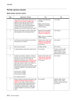
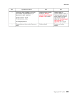
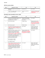
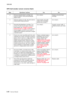
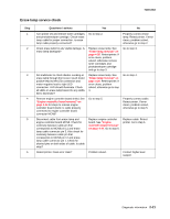
7100-XXX Step Questions / actions 7 Disconnect cable from engine controller board POCN. Check the following on disconnected cable connector: Pin 21 to pin 22-24VDC Pin 13 to pin 14-5VDC Are voltages present? 8 Reassemble and retest printer. Does error clear? Transfer belt unit service check Yes No Replace engine controller board. See "Engine controller board removal" on page 4-34. Go step 8. Problem solved. Replace cable that connects ACN1 on LVPS to POCN on engine controller board. Remove RIP board cage to gain access to cable. See "System board cage removal" on page 4-38. Go to step 8. Contact next level of support. Step 1 2 3 4 5 Questions / actions Yes No Open rear cover assembly, and check transfer belt unit markers for stains. Are markers stained? Clean belt marker area with cotton cloth. If problem persists, go to step 2. Go to step 2. Remove transfer belt unit, and observe markers on side. Are belt markers deformed or does transfer belt seem hard to rotate? Replace transfer belt unit. See "Transfer belt unit removal" on page 4-5. Reinstall transfer belt unit. Go to step 3. Turn printer off, and remove engine controller board shield. See "Engine controller board removal" on page 4-34 for steps to remove engine controller board shield. Are cables properly connected to engine controller board connectors MCN9 and POCN? Go to step 4. Properly connect cables. If problem persists, go to step 4. Ensure rear cover assembly and front cover assembly are closed. Override top interlock switch, and turn printer on. Wait until printer displays error, and remove MCN9 from engine controller board. Check for 5 VDC between MCN9 pin 1 (on engine controller board) and ground (you can touch negative lead of voltmeter to metal frame to obtain ground.) Is voltage present and correct? Engine controller board is providing 5 VDC to marker sensor. Replace transfer belt marker sensor. Marker sensor is part of a bracket assembly. See "Bracket assembly removal" on page 4-30. If problem persists, replace engine controller board. See "Engine controller board removal" on page 4-34. Go to step 5. On engine controller board, reconnect MCN9 and disconnect cable from POCN. On cable disconnected from POCN, check for 5 VDC from pin 13 to ground (you can touch negative lead of voltmeter to metal frame to obtain ground.) Is voltage present and correct? LVPS is providing 5 VDC to engine controller board. Replace faulty engine controller board. See "Engine controller board removal" on page 4-34. Replace LVPS. See "Low voltage power supply (LVPS) with cage removal" on page 4-40. Diagnostic information 2-17
-
 1
1 -
2
-
3
-
4
-
5
-
6
-
7
-
8
-
9
-
10
-
11
-
12
-
13
-
14
-
15
-
16
-
17
-
18
-
19
-
20
-
21
-
22
-
23
-
24
-
25
-
26
-
27
-
28
-
29
-
30
-
31
-
32
-
33
-
34
-
35
-
36
-
37
-
38
-
39
-
40
-
41
-
42
-
43
-
44
-
45
-
46
-
47
-
48
-
49
-
 50
50 -
 51
51 -
 52
52 -
 53
53 -
 54
54 -
 55
55 -
 56
56 -
 57
57 -
 58
58 -
 59
59 -
 60
60 -
61
-
62
-
63
-
64
-
65
-
66
-
67
-
68
-
69
-
70
-
71
-
72
-
73
-
74
-
75
-
76
-
77
-
78
-
79
-
80
-
81
-
82
-
83
-
84
-
85
-
86
-
87
-
88
-
89
-
90
-
91
-
92
-
93
-
94
-
95
-
96
-
97
-
98
-
99
-
100
-
101
-
102
-
103
-
104
-
105
-
106
-
107
-
108
-
109
-
110
-
111
-
112
-
113
-
114
-
115
-
116
-
117
-
118
-
119
-
120
-
121
-
122
-
123
-
124
-
125
-
126
-
127
-
128
-
129
-
130
-
131
-
132
-
133
-
134
-
135
-
136
-
137
-
138
-
139
-
140
-
141
-
142
-
143
-
144
-
145
-
146
-
147
-
148
-
149
-
150
-
151
-
152
-
153
-
154
-
155
-
156
-
157
-
158
-
159
-
160
-
161
-
162
-
163
-
164
-
165
-
166
-
167
-
168
-
169
-
170
-
171
-
172
-
173
-
174
-
175
-
176
-
177
-
178
-
179
-
180
-
181
-
182
-
183
-
184
-
185
-
186
-
187
-
188
-
189
-
190
-
191
-
192
-
193
-
194
-
195
-
196
-
197
-
198
-
199
-
200
-
201
-
202
-
203
-
204
-
205
-
206
-
207
-
208
-
209
-
210
-
211
-
212
-
213
-
214
-
215
-
216
-
217
-
218
-
219
-
220
-
221
-
222
-
223
-
224
-
225
-
226
-
227
-
228
-
229
-
230
-
231
-
232
-
233
-
234
-
235
-
236
-
237
-
238
-
239
-
240
-
241
-
242
-
243
-
244
 |
 |
