Philips DVDR3455H User manual - Page 16
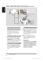
Connecting the video cable - recorder
 |
UPC - 609585112773
View all Philips DVDR3455H manuals
Add to My Manuals
Save this manual to your list of manuals |
Page 16 highlights
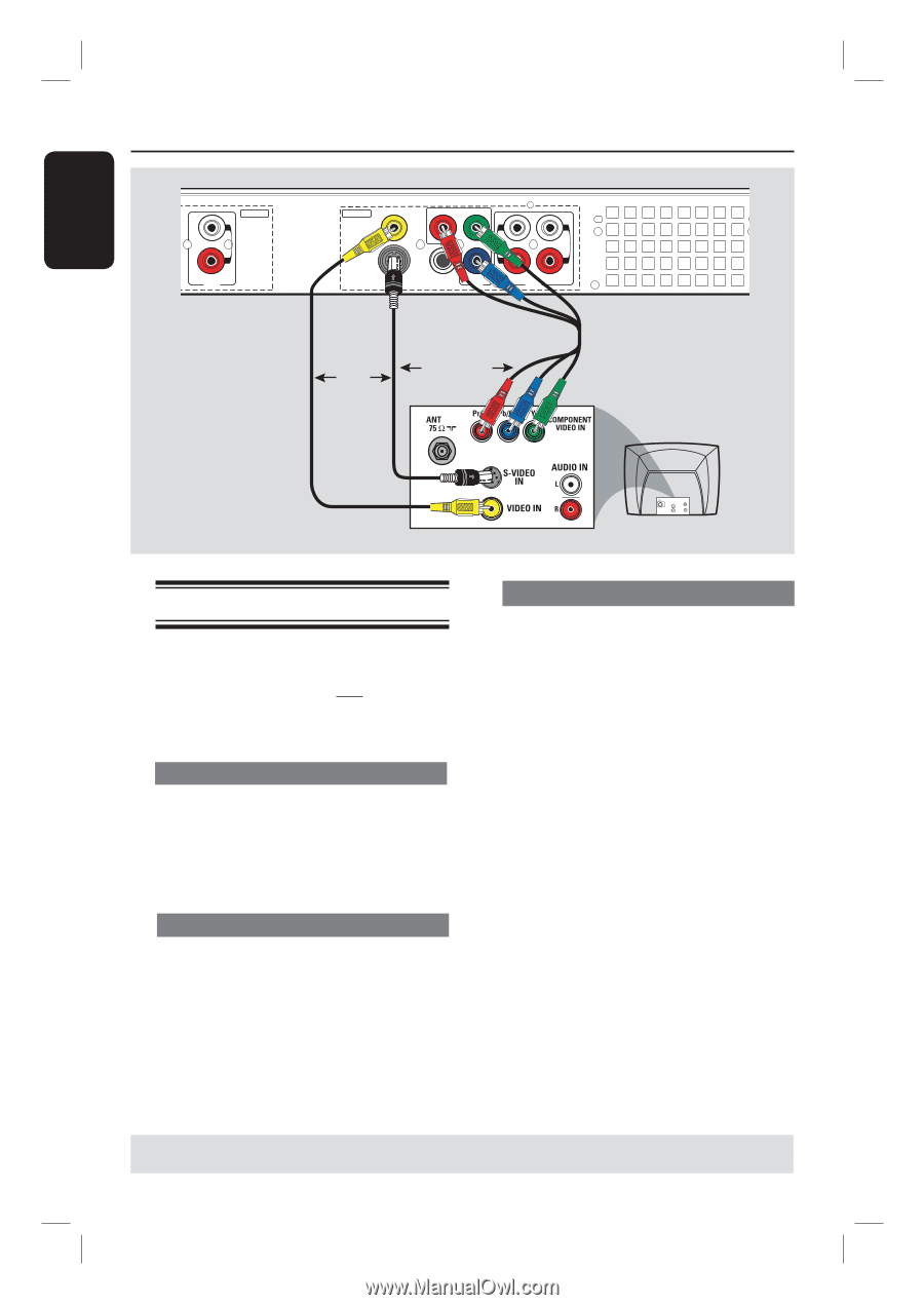
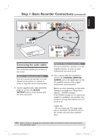
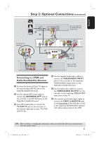
English Step 1: Basic Recorder Connections (continued) INPUT L R AUDIO Option 1 OUTPUT VIDEO (CVBS) PR COMPONENT Y VIDEO OUT 1 L L OUT 2 R R S-VIDEO (Y/C) COAXIAL PB (DIGITAL AUDIO) OUT 3 AUDIO Option 2 OR OR Option 3 TV AU D IO O UT S-V ID E O IN V ID E O IN Connecting the video cable This connection enables you to view the disc playback from the recorder. You only need to choose one of the options below to make your video connection. Option 1: Using Video (CVBS) jack Use the supplied audio/video cables (yellow plug) to connect the VIDEO (CVBS)-OUT1 jack on the recorder to the video input jack (or labeled as A/V In, Video In or Composite) on the TV. Option 2: Using S-Video jack Use an S-video cable (not supplied) to connect the S-VIDEO (Y/C) - OUT2 jack on the recorder to the S-Video input jack (or labeled as Y/C or S-VHS) on the TV. Option 3 : Using Component Video A Use the component video cables (red/ blue/green - not supplied) to connect the Y PB PR -OUT3 jacks on the recorder to the corresponding component video input jacks (or labeled as Y Pb/Cb Pr/Cr or YUV) on the TV. B If your TV accepts Progressive Scan signal, see the chapter "Setup Menu Options - PREFERENCE settings" for detailed set up. IMPORTANT! The progressive scan video quality is only available through a Y PB PR connection and a progressive TV is required. It is strongly advised to complete the recorder installation first, before enabling the progressive scan feature. TIPS: Before making or changing any connections, make sure that all the devices are disconnected from the power outlet. 16 1_dvdr3455H_eng_21832.indd 16 2007-06-11 11:23:24 AM
-
 1
1 -
2
-
3
-
4
-
5
-
6
-
7
-
8
-
9
-
10
-
 11
11 -
 12
12 -
 13
13 -
 14
14 -
 15
15 -
 16
16 -
 17
17 -
 18
18 -
 19
19 -
 20
20 -
 21
21 -
22
-
23
-
24
-
25
-
26
-
27
-
28
-
29
-
30
-
31
-
32
-
33
-
34
-
35
-
36
-
37
-
38
-
39
-
40
-
41
-
42
-
43
-
44
-
45
-
46
-
47
-
48
-
49
-
50
-
51
-
52
-
53
-
54
-
55
-
56
-
57
-
58
-
59
-
60
-
61
-
62
-
63
-
64
-
65
-
66
-
67
-
68
-
69
-
70
-
71
-
72
-
73
-
74
-
75
-
76
-
77
-
78
-
79
-
80
-
81
-
82
-
83
 |
 |