Philips DVDR3455H User manual - Page 19
Step 2: Optional Connections
 |
UPC - 609585112773
View all Philips DVDR3455H manuals
Add to My Manuals
Save this manual to your list of manuals |
Page 19 highlights
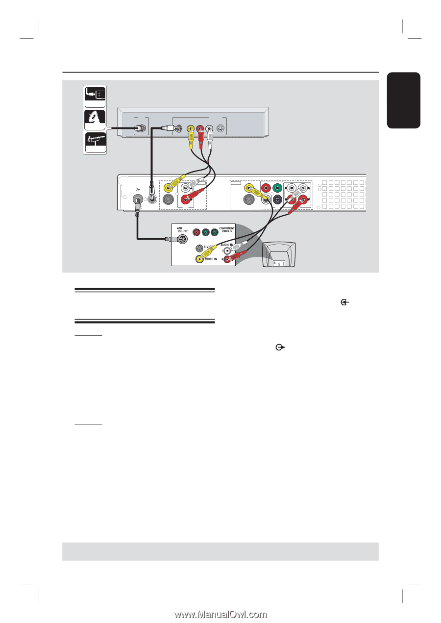
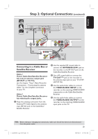
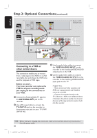
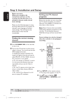
English Step 2: Optional Connections (continued) CABLE SATELLITE ANTENNA A IN B OUT RF VIDEO AUDIO R L S-VIDEO D Back of a Cable Box or Satellite Receiver (Example only) VIDEO (CVBS) EXT 1 TV-OUT ANTENNA-IN EXT 2 S-VIDEO (Y/C) INPUT L R AUDIO C OUTPUT VIDEO (CVBS) PR COMPONENT Y VIDEO OUT 1 L L OUT 2 R R S-VIDEO (Y/C) COAXIAL PB (DIGITAL AUDIO) OUT 3 AUDIO E TV AU D IO O UT S-V ID E O IN V ID E O IN Connecting to a Cable Box or Satellite Receiver Option 1 If your Cable Box/Satellite Receiver has only an antenna output jack (RF OUT or TO TV), see the chapter "Step 1: Basic Recorder Connections - Connecting the antenna cables" for the complete connection to your TV. Option 2 If your Cable Box/Satellite Receiver has video/audio output jacks, A Keep the existing connection from the Antenna/TV Cable Signal to the antenna input (RF-IN) jack on the Cable Box/ Satellite Receiver. B Use the supplied RF coaxial cable to connect the ANTENNA-IN jack on the recorder to the RF OUT jack on the Cable Box/Satellite Receiver. C Use a RF coaxial cable to connect the TV-OUT jack on the recorder to the antenna input jack on your TV (VHF/ UHF RF IN.) D Use the audio/video cables to connect the VIDEO/AUDIO INPUT on the recorder to the matching VIDEO/AUDIO output jacks on the Cable Box/Satellite Receiver. E Use the audio/video cables to connect the VIDEO/AUDIO OUTPUT on the recorder to the matching VIDEO/AUDIO input jacks on the TV. TIPS: Before making or changing any connections, make sure that all the devices are disconnected from the power outlet. 19 1_dvdr3455H_eng_21832.indd 19 2007-06-11 11:23:24 AM
-
 1
1 -
2
-
3
-
4
-
5
-
6
-
7
-
8
-
9
-
10
-
11
-
12
-
13
-
 14
14 -
 15
15 -
 16
16 -
 17
17 -
 18
18 -
 19
19 -
 20
20 -
 21
21 -
 22
22 -
 23
23 -
 24
24 -
25
-
26
-
27
-
28
-
29
-
30
-
31
-
32
-
33
-
34
-
35
-
36
-
37
-
38
-
39
-
40
-
41
-
42
-
43
-
44
-
45
-
46
-
47
-
48
-
49
-
50
-
51
-
52
-
53
-
54
-
55
-
56
-
57
-
58
-
59
-
60
-
61
-
62
-
63
-
64
-
65
-
66
-
67
-
68
-
69
-
70
-
71
-
72
-
73
-
74
-
75
-
76
-
77
-
78
-
79
-
80
-
81
-
82
-
83
 |
 |