Sennheiser ADN D1 Instructions for Use - Page 14
ADN PS power supply
 |
View all Sennheiser ADN D1 manuals
Add to My Manuals
Save this manual to your list of manuals |
Page 14 highlights
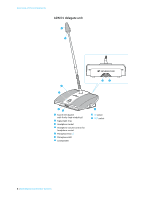
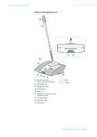
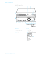
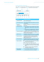
Overview of the components ADN PS power supply 1 2 3 4 5 1 ADN PS PORT I 1 2 PORT II 1 2 DATA CU/PS PS PORT I & PORT II: max. 5.25A sum 67 8 90 A D B E 100 - 240V 50/60Hz 385W C 15 A Front view 1 Rack mount "ears" 2 On/off switch 3 PORT I status LED for outputs 1 and 2 4 PORT II status LED for outputs 1 and 2 5 POWER status LED B Rear view 6 PORT I socket - output 1 (RJ 45) for connec- tion of conference units 7 PORT I socket - output 2 (RJ 45) for connec- tion of conference units 8 PORT II socket - output 1 (RJ 45) for connection of conference units 9 PORT II socket - output 2 (RJ 45) for connection of conference units < DATA CU/PS input socket (RJ 45) for connection of ADN CU1 central unit or ADN PS power supply A DATA PS output socket (RJ 45) for connection of additional ADN PS B Fans C Mains socket D Hazard warnings E Type plate Overview of the status LEDs Status LED POWER 5 PORT I 3/Port II 4 output 1/2 Color Meaning green ADN PS is switched on - Not used, switched off orange Conference units are connected in strings green Conference units are connected in redundant ring topology via outputs 1 and 2 flashing Error in a cable string; orange output is switched off ADN Digital Conference System | 13
-
 1
1 -
2
-
3
-
4
-
5
-
6
-
7
-
8
-
 9
9 -
 10
10 -
 11
11 -
 12
12 -
 13
13 -
 14
14 -
 15
15 -
 16
16 -
 17
17 -
 18
18 -
 19
19 -
20
-
21
-
22
-
23
-
24
-
25
-
26
-
27
-
28
-
29
-
30
-
31
-
32
-
33
-
34
-
35
-
36
-
37
-
38
-
39
-
40
-
41
-
42
-
43
-
44
-
45
-
46
-
47
-
48
-
49
-
50
-
51
-
52
-
53
-
54
-
55
-
56
-
57
-
58
-
59
-
60
-
61
-
62
-
63
-
64
-
65
-
66
-
67
-
68
-
69
-
70
-
71
-
72
-
73
-
74
-
75
-
76
-
77
-
78
-
79
-
80
-
81
-
82
-
83
-
84
-
85
-
86
-
87
-
88
-
89
-
90
-
91
-
92
-
93
-
94
-
95
-
96
-
97
-
98
-
99
-
100
-
101
-
102
-
103
-
104
-
105
-
106
-
107
-
108
-
109
-
110
-
111
-
112
-
113
-
114
-
115
-
116
-
117
-
118
-
119
-
120
-
121
-
122
-
123
-
124
-
125
-
126
-
127
-
128
-
129
-
130
-
131
-
132
-
133
-
134
-
135
-
136
-
137
-
138
-
139
-
140
-
141
-
142
-
143
-
144
-
145
-
146
-
147
-
148
-
149
-
150
-
151
-
152
-
153
-
154
-
155
-
156
-
157
-
158
-
159
-
160
-
161
-
162
-
163
-
164
-
165
-
166
-
167
-
168
-
169
 |
 |
