Sennheiser ADN D1 Instructions for Use - Page 42
Switching the conference system on/off, Status LED, Color, Meaning
 |
View all Sennheiser ADN D1 manuals
Add to My Manuals
Save this manual to your list of manuals |
Page 42 highlights
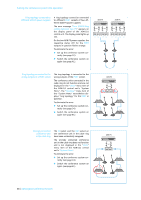
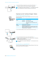
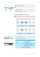
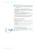
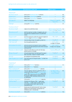
Putting the conference system into operation IN -- AUDIO -- OUT PORT II PORT I 2x 52.8V 1.75A 100-240V~ 50/60Hz 240W B ̈ Use a network cable (Cat5) to connect the Ethernet socket B of the central unit to the network interface of your PC. You can also connect the PC and the central unit using a switch or similar. ̈ Install the "Conference Manager" software supplied on the DVD-ROM on your connected PC (see page 82). ̈ Configure the network as described in the chapter "Preparing the Windows version of the software for use" on page 81. Switching the conference system on/off The ADN PS power supplies can only be switched on when the ADN CU1 central unit and the previous ADN PS connected in series are also switched on. You can set up your conference system so that you can increase or reduce the number of conference units used by simply switching individual ADN PS on or off. ADN CU1 ADN PS ADN PS ADN PS ADN PS ESC ON ON ON OFF OFF ADN CU1 ESC ADN PS ON ON ADN PS ADN PS OFF ON ADN PS ON ADN CU1 ESC 1 ADN PS 2 34 5 Switching the conference system on ̈ On the ADN CU1 central unit and the ADN PS power supplies, set the on/off switch 1 or 2 to position "I". The central unit switches on and its display panel lights up. The power supplies switch on and their status LEDs light up: Status LED POWER 5 PORT I 3/Port II 4 output 1/2 Color Meaning green ADN PS is switched on - Not used, switched off orange Conference units are connected in strings green Conference units are connected in redundant ring topology via output 1 and 2 flashing Error in a cable string; orange output is switched off ADN Digital Conference System | 41
-
 1
1 -
2
-
3
-
4
-
5
-
6
-
7
-
8
-
9
-
10
-
11
-
12
-
13
-
14
-
15
-
16
-
17
-
18
-
19
-
20
-
21
-
22
-
23
-
24
-
25
-
26
-
27
-
28
-
29
-
30
-
31
-
32
-
33
-
34
-
35
-
36
-
 37
37 -
 38
38 -
 39
39 -
 40
40 -
 41
41 -
 42
42 -
 43
43 -
 44
44 -
 45
45 -
 46
46 -
 47
47 -
48
-
49
-
50
-
51
-
52
-
53
-
54
-
55
-
56
-
57
-
58
-
59
-
60
-
61
-
62
-
63
-
64
-
65
-
66
-
67
-
68
-
69
-
70
-
71
-
72
-
73
-
74
-
75
-
76
-
77
-
78
-
79
-
80
-
81
-
82
-
83
-
84
-
85
-
86
-
87
-
88
-
89
-
90
-
91
-
92
-
93
-
94
-
95
-
96
-
97
-
98
-
99
-
100
-
101
-
102
-
103
-
104
-
105
-
106
-
107
-
108
-
109
-
110
-
111
-
112
-
113
-
114
-
115
-
116
-
117
-
118
-
119
-
120
-
121
-
122
-
123
-
124
-
125
-
126
-
127
-
128
-
129
-
130
-
131
-
132
-
133
-
134
-
135
-
136
-
137
-
138
-
139
-
140
-
141
-
142
-
143
-
144
-
145
-
146
-
147
-
148
-
149
-
150
-
151
-
152
-
153
-
154
-
155
-
156
-
157
-
158
-
159
-
160
-
161
-
162
-
163
-
164
-
165
-
166
-
167
-
168
-
169
 |
 |
