Sennheiser ADN D1 Instructions for Use - Page 35
Setting up large conference system comprising ADN PS power supplies
 |
View all Sennheiser ADN D1 manuals
Add to My Manuals
Save this manual to your list of manuals |
Page 35 highlights
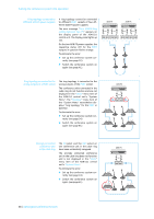
Putting the conference system into operation Setting up large conference system comprising ADN PS power supplies conference units connected in redundant ring topology In large conference systems with up to 400 conference units, the redundant ring topology ensures that, should one conference unit or system cable fail or be manipulated, all other conference units of the cable ring will continue to function reliably. When the conference units are connected in ring topology, one ADN PS power supply can power approx. 30-40 conference units. To ensure full operational reliability in a redundant ring topology, the hardware of the ADN C1 and ADN D1 has been revised. If you combine conference units with hardware revision 1 (no marking on the type plate) and conference units with hardware revision 2 ("HW: v2" is printed on the type plate), fail-safe operation is only possible to a limited extent (see also page 68). ̈ In a redundant ring topology, only use conference units with hardware revision 2. IN OUT Connecting conference units connected in a cable ring to the ADN PS power supply The following describes how to connect one cable ring to an ADN PS power supply. If necessary, repeat these steps for a second cable ring and additional ADN PS power supplies. ̈ Connect the required number of ADN PS power supplies to the ADN CU1 central unit (see page 31). ̈ Use a system cable to connect output 1 6 of the PORT I socket of the ADN PS power supply to the IN socket µ of the first conference unit. ̈ Use a system cable to connect the OUT socket ¸ of the first conference unit to the IN socket µ of the second conference unit. ̈ Repeat these steps for additional conference units. ̈ Use a system cable to connect the OUT socket ¸ of the last conference unit in the cable ring to output 2 7 of the PORT I socket of the ADN PS power supply. ̈ If necessary, repeat all steps for a second cable ring on PORT II and the additional ADN PS power supplies. 34 | ADN Digital Conference System
-
 1
1 -
2
-
3
-
4
-
5
-
6
-
7
-
8
-
9
-
10
-
11
-
12
-
13
-
14
-
15
-
16
-
17
-
18
-
19
-
20
-
21
-
22
-
23
-
24
-
25
-
26
-
27
-
28
-
29
-
 30
30 -
 31
31 -
 32
32 -
 33
33 -
 34
34 -
 35
35 -
 36
36 -
 37
37 -
 38
38 -
 39
39 -
 40
40 -
41
-
42
-
43
-
44
-
45
-
46
-
47
-
48
-
49
-
50
-
51
-
52
-
53
-
54
-
55
-
56
-
57
-
58
-
59
-
60
-
61
-
62
-
63
-
64
-
65
-
66
-
67
-
68
-
69
-
70
-
71
-
72
-
73
-
74
-
75
-
76
-
77
-
78
-
79
-
80
-
81
-
82
-
83
-
84
-
85
-
86
-
87
-
88
-
89
-
90
-
91
-
92
-
93
-
94
-
95
-
96
-
97
-
98
-
99
-
100
-
101
-
102
-
103
-
104
-
105
-
106
-
107
-
108
-
109
-
110
-
111
-
112
-
113
-
114
-
115
-
116
-
117
-
118
-
119
-
120
-
121
-
122
-
123
-
124
-
125
-
126
-
127
-
128
-
129
-
130
-
131
-
132
-
133
-
134
-
135
-
136
-
137
-
138
-
139
-
140
-
141
-
142
-
143
-
144
-
145
-
146
-
147
-
148
-
149
-
150
-
151
-
152
-
153
-
154
-
155
-
156
-
157
-
158
-
159
-
160
-
161
-
162
-
163
-
164
-
165
-
166
-
167
-
168
-
169
 |
 |
