Sony DVWM2000 Product Manual (Operation Manual 1st Edition (Revised 6)) - Page 107
Function Menu, 11-1 Overview of the Function Menu, 11-1-1 Function Menu Configuration
 |
View all Sony DVWM2000 manuals
Add to My Manuals
Save this manual to your list of manuals |
Page 107 highlights
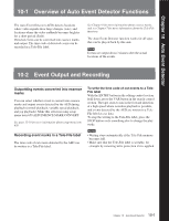
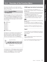
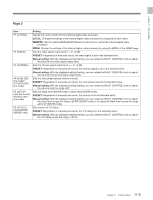
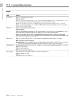
Cha Chapterpt11er 11 Function MenuFunction Menu 11-1 Overview of the Function Menu The function menu allows you to make frequently made settings, such as selection of input video signals and time code settings. 11-1-1 Function Menu Configuration The function menu consists of seven pages by factory default: the HOME page and five pages numbered 1 to 6. You can also display the HOME2 page by setting user-defined function keys. The following icons appear at the left edge of the menu display section to denote the current page. 1 : HOME page 1: Page 1 2: Page 2 3: Page 3 4: Page 4 5: Page 5 6: Page 6 2: HOME 2 page Each page has a menu display section made up of an upper and lower part. The upper part displays the menu items (functions) in the page, and the lower part displays the menu item settings. The figure below shows the menu display section in the HOME page. Menu items (functions) VID. IN PB/EE CONFI CTL/TC MENU TCGSET Y-R,B PB OFF TC HOME F1 F2 F3 F4 F5 F6 Settings (values) HOME2 page (user-defined function keys) Up to six function keys can be defined (i.e. six functions can be assigned to the F1 to F6 buttons in the HOME2 page). You can select and define the following function keys: • Functions selected from the function menu items in the HOME page and menu pages 1 to 4 • Function key to display the setting for setup menu item 211 (REMOTE1 PORT) and to carry out the operation when the menu item setting is "panel". Note By factory default, no function keys are defined in the HOME2 page. It is not possible to display the HOME2 page unless you have defined at least one function key in that page. For details on defining user-defined function keys in the HOME2 page, refer to the Maintenance Manual Volume 1. Page 6 You can define up to six setup menu items (assign six setup menu items to the F1 to F6 buttons) and register them on page 6. Note There is nothing defined on page 6 when the unit is shipped from the factory. For more information about defining setup menu items for page 6, refer to the Maintenance Manual Volume 1. In the figure above, Y-R,B (analog component signals) is selected as the setting for VID.IN, the menu item for button F1. This manual refers to this as "F1 (VID.IN) in function menu HOME page is set to Y-R,B." 11-1 Chapter 11 Function Menu
-
 1
1 -
2
-
3
-
4
-
5
-
6
-
7
-
8
-
9
-
10
-
11
-
12
-
13
-
14
-
15
-
16
-
17
-
18
-
19
-
20
-
21
-
22
-
23
-
24
-
25
-
26
-
27
-
28
-
29
-
30
-
31
-
32
-
33
-
34
-
35
-
36
-
37
-
38
-
39
-
40
-
41
-
42
-
43
-
44
-
45
-
46
-
47
-
48
-
49
-
50
-
51
-
52
-
53
-
54
-
55
-
56
-
57
-
58
-
59
-
60
-
61
-
62
-
63
-
64
-
65
-
66
-
67
-
68
-
69
-
70
-
71
-
72
-
73
-
74
-
75
-
76
-
77
-
78
-
79
-
80
-
81
-
82
-
83
-
84
-
85
-
86
-
87
-
88
-
89
-
90
-
91
-
92
-
93
-
94
-
95
-
96
-
97
-
98
-
99
-
100
-
101
-
 102
102 -
 103
103 -
 104
104 -
 105
105 -
 106
106 -
 107
107 -
 108
108 -
 109
109 -
 110
110 -
 111
111 -
 112
112 -
113
-
114
-
115
-
116
-
117
-
118
-
119
-
120
-
121
-
122
-
123
-
124
-
125
-
126
-
127
-
128
-
129
-
130
-
131
-
132
-
133
-
134
-
135
-
136
-
137
-
138
-
139
-
140
-
141
-
142
-
143
-
144
-
145
-
146
-
147
-
148
-
149
-
150
-
151
-
152
-
153
-
154
-
155
-
156
-
157
-
158
-
159
-
160
-
161
-
162
-
163
-
164
 |
 |