Sony DVWM2000 Product Manual (Operation Manual 1st Edition (Revised 6)) - Page 28
Switch Panel, Memory stick slot, KEY INHI switch, PANEL SELECT switch, FRONT
 |
View all Sony DVWM2000 manuals
Add to My Manuals
Save this manual to your list of manuals |
Page 28 highlights
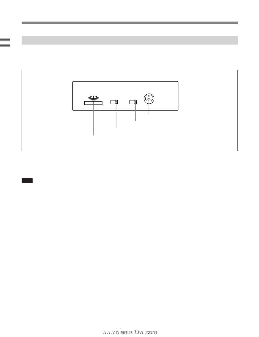
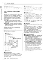
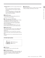
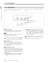
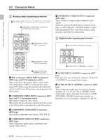
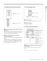
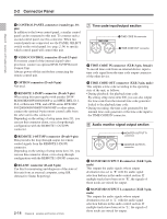
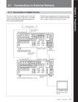
2-1 Control Panels 2-1-3 Switch Panel To access the switch panel, open the lower control panel. On how to open the lower control panel, see the figure on page 2-1. Chapter 2 Location and Function of Parts KEY INHI PANEL SEL CONTROL PANEL ON OFF REAR FRONT 4 CONTROL PANEL connector 3 PANEL SELECT switch 2 KEY INHI switch 1 Memory stick slot 1 Memory stick slot Use this to update the firmware. You can also save or load setup menu settings onto the Memory Stick. Note After inserting a Memory Stick, allow at least five seconds to elapse before removing it. For details on firmware update and save or load setup menu settings, see Section 13-1 "Overview of Setup Utility Menu Functions" and refer to the Maintenance Manual Volume 1. 2 KEY INHI switch Moving this switch to the ON position disables the controls on the upper and lower control panels. You can specify which buttons and knobs are disabled in setup menu item 118. 3 PANEL SELECT switch In addition to the lower control panel, you can connect a similar control panel to this unit. When two control panels are connected to the unit, the PANEL SELECT switch is used to specify which panel be enabled to control the unit. FRONT: Enables the control panel connected to the CONTROL PANEL connector on the switch panel. REAR: Enables the control panel connected to the CONTROL PANEL connector on the connector panel. When setup menu item 117 is set to PARA, this switch position also enables the control panel connected to the CONTROL PANEL connector on the switch panel. 4 CONTROL PANEL connector (10-pin, round type) Plug in the lower control panel connection cable. 2-14 Chapter 2 Location and Function of Parts
-
 1
1 -
2
-
3
-
4
-
5
-
6
-
7
-
8
-
9
-
10
-
11
-
12
-
13
-
14
-
15
-
16
-
17
-
18
-
19
-
20
-
21
-
22
-
 23
23 -
 24
24 -
 25
25 -
 26
26 -
 27
27 -
 28
28 -
 29
29 -
 30
30 -
 31
31 -
 32
32 -
 33
33 -
34
-
35
-
36
-
37
-
38
-
39
-
40
-
41
-
42
-
43
-
44
-
45
-
46
-
47
-
48
-
49
-
50
-
51
-
52
-
53
-
54
-
55
-
56
-
57
-
58
-
59
-
60
-
61
-
62
-
63
-
64
-
65
-
66
-
67
-
68
-
69
-
70
-
71
-
72
-
73
-
74
-
75
-
76
-
77
-
78
-
79
-
80
-
81
-
82
-
83
-
84
-
85
-
86
-
87
-
88
-
89
-
90
-
91
-
92
-
93
-
94
-
95
-
96
-
97
-
98
-
99
-
100
-
101
-
102
-
103
-
104
-
105
-
106
-
107
-
108
-
109
-
110
-
111
-
112
-
113
-
114
-
115
-
116
-
117
-
118
-
119
-
120
-
121
-
122
-
123
-
124
-
125
-
126
-
127
-
128
-
129
-
130
-
131
-
132
-
133
-
134
-
135
-
136
-
137
-
138
-
139
-
140
-
141
-
142
-
143
-
144
-
145
-
146
-
147
-
148
-
149
-
150
-
151
-
152
-
153
-
154
-
155
-
156
-
157
-
158
-
159
-
160
-
161
-
162
-
163
-
164
 |
 |