Sony DVWM2000 Product Manual (Operation Manual 1st Edition (Revised 6)) - Page 31
Digital signal input/output Power supply External device connectors
 |
View all Sony DVWM2000 manuals
Add to My Manuals
Save this manual to your list of manuals |
Page 31 highlights
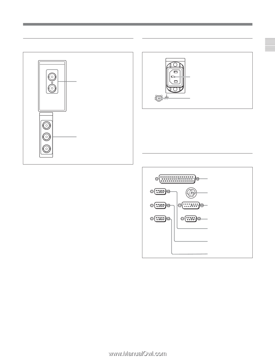
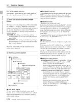
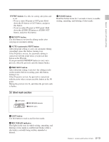
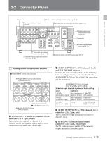
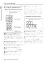
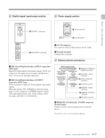
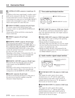
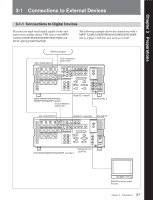
Chapter 2 Location and Function of Parts 4 Digital signal input/output section 5 Power supply section SDI INPUT 1 SDI INPUT connectors 1 AC IN connector 2 Ground terminal SDI OUTPUT 1 2 3(SUPER) 2 SDI OUTPUT connectors 1 AC IN connector Use a power cord to connect this to an AC outlet. 2 Ground terminal Connect this to ground. 6 External device connectors 1 SDI (Serial Digital Interface) INPUT connectors (BNC type) Input D1 format digital video/audio signals. Of the two connectors, the upper one is for input, and the lower one is for an active-through connection. 2 SDI (Serial Digital Interface) OUTPUT connectors (BNC type) These connectors output D1 format digital video/audio signals. When the setting of F4 (CHARA) in function menu page 4 is ON, connector 3 (SUPER) outputs a signal with superimposed time code, menu settings, alarm messages, and other text information. REMOTE 2 PARALLEL I/O(50P) REMOTE 1-IN(9P) CONTROL PANEL 1 REMOTE 2 PARALLEL I/O(50P) connector REMOTE 1-OUT(9P) RS232C VIDEO CONTROL 2 CONTROL PANEL connector 3 VIDEO CONTROL connector (OPTION) 4 OPTION connector 5 REMOTE 1-IN(9P) connector 6 REMOTE 1-OUT(9P) connector 7 RS-232C connector 1 REMOTE 2 PARALLEL I/O(50P) connector (D-sub 50-pin) Connect remote control signals from an external device. For details, refer to the Installation Manual. 2-17 Chapter 2 Location and Function of Parts
-
 1
1 -
2
-
3
-
4
-
5
-
6
-
7
-
8
-
9
-
10
-
11
-
12
-
13
-
14
-
15
-
16
-
17
-
18
-
19
-
20
-
21
-
22
-
23
-
24
-
25
-
 26
26 -
 27
27 -
 28
28 -
 29
29 -
 30
30 -
 31
31 -
 32
32 -
 33
33 -
 34
34 -
 35
35 -
 36
36 -
37
-
38
-
39
-
40
-
41
-
42
-
43
-
44
-
45
-
46
-
47
-
48
-
49
-
50
-
51
-
52
-
53
-
54
-
55
-
56
-
57
-
58
-
59
-
60
-
61
-
62
-
63
-
64
-
65
-
66
-
67
-
68
-
69
-
70
-
71
-
72
-
73
-
74
-
75
-
76
-
77
-
78
-
79
-
80
-
81
-
82
-
83
-
84
-
85
-
86
-
87
-
88
-
89
-
90
-
91
-
92
-
93
-
94
-
95
-
96
-
97
-
98
-
99
-
100
-
101
-
102
-
103
-
104
-
105
-
106
-
107
-
108
-
109
-
110
-
111
-
112
-
113
-
114
-
115
-
116
-
117
-
118
-
119
-
120
-
121
-
122
-
123
-
124
-
125
-
126
-
127
-
128
-
129
-
130
-
131
-
132
-
133
-
134
-
135
-
136
-
137
-
138
-
139
-
140
-
141
-
142
-
143
-
144
-
145
-
146
-
147
-
148
-
149
-
150
-
151
-
152
-
153
-
154
-
155
-
156
-
157
-
158
-
159
-
160
-
161
-
162
-
163
-
164
 |
 |