Sony DVWM2000 Product Manual (Operation Manual 1st Edition (Revised 6)) - Page 35
Reference Signals for Video Output and Servo System
 |
View all Sony DVWM2000 manuals
Add to My Manuals
Save this manual to your list of manuals |
Page 35 highlights
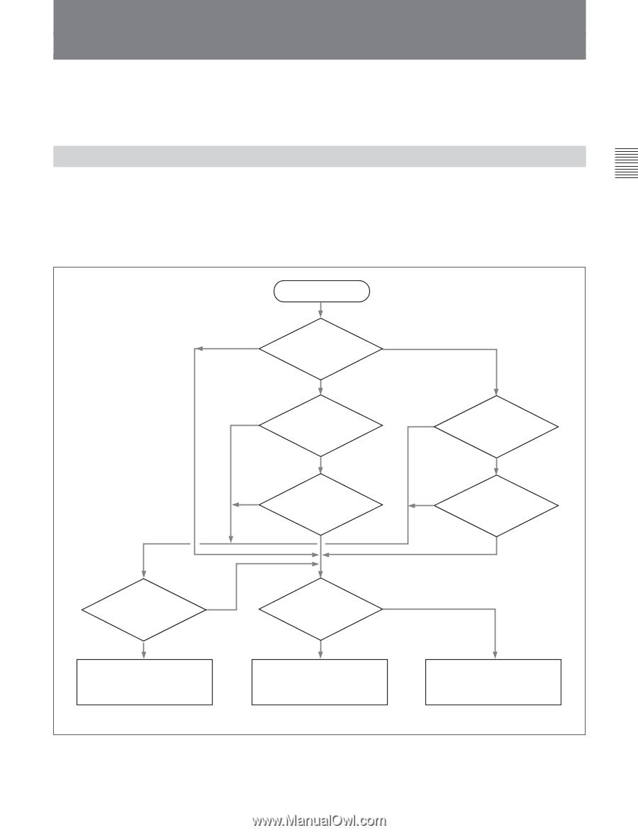
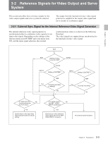
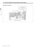
Chapter 3 Preparations 3-2 Reference Signals for Video Output and Servo System This section describes how reference signals for the video output signals and servo system are selected. The output from the internal reference video signal generator is supplied to the output video signal and servo circuits as a reference signal. 3-2-1 External Sync Signal for the Internal Reference Video Signal Generator The internal reference video signal generator is synchronized either to a reference video signal or to an input video signal. Depending on the settings of the function menu item OUTREF and setup menu item 309, and the input signal selection, the external synchronization status is as shown in the following flowchart. The video signals are output always synchronized to the internal reference video signal. Start EXT Setting of setup menu item 309? INPUT AUTO2 Setting of OUTREF? AUTO1 INPUT Setting of OUTREF ? REF Yes Currently recording or editing? No REF Yes Currently recording? No Is a signal input to the No connector selected with the VID.IN setting? Yes Synchronize to the input video signal selected with the VID.IN setting. Is a signal input to No the REF. VIDEO INPUT connector? Yes Synchronize to the reference video signal input to the REF. VIDEO INPUT connector. No external synchronization 3-3 Chapter 3 Preparations
-
 1
1 -
2
-
3
-
4
-
5
-
6
-
7
-
8
-
9
-
10
-
11
-
12
-
13
-
14
-
15
-
16
-
17
-
18
-
19
-
20
-
21
-
22
-
23
-
24
-
25
-
26
-
27
-
28
-
29
-
 30
30 -
 31
31 -
 32
32 -
 33
33 -
 34
34 -
 35
35 -
 36
36 -
 37
37 -
 38
38 -
 39
39 -
 40
40 -
41
-
42
-
43
-
44
-
45
-
46
-
47
-
48
-
49
-
50
-
51
-
52
-
53
-
54
-
55
-
56
-
57
-
58
-
59
-
60
-
61
-
62
-
63
-
64
-
65
-
66
-
67
-
68
-
69
-
70
-
71
-
72
-
73
-
74
-
75
-
76
-
77
-
78
-
79
-
80
-
81
-
82
-
83
-
84
-
85
-
86
-
87
-
88
-
89
-
90
-
91
-
92
-
93
-
94
-
95
-
96
-
97
-
98
-
99
-
100
-
101
-
102
-
103
-
104
-
105
-
106
-
107
-
108
-
109
-
110
-
111
-
112
-
113
-
114
-
115
-
116
-
117
-
118
-
119
-
120
-
121
-
122
-
123
-
124
-
125
-
126
-
127
-
128
-
129
-
130
-
131
-
132
-
133
-
134
-
135
-
136
-
137
-
138
-
139
-
140
-
141
-
142
-
143
-
144
-
145
-
146
-
147
-
148
-
149
-
150
-
151
-
152
-
153
-
154
-
155
-
156
-
157
-
158
-
159
-
160
-
161
-
162
-
163
-
164
 |
 |