Sony DVWM2000 Product Manual (Operation Manual 1st Edition (Revised 6)) - Page 16
Upper Control Panel, POWER switch, REMOTE buttons and RS-232C indicator, RS-232C indicator
 |
View all Sony DVWM2000 manuals
Add to My Manuals
Save this manual to your list of manuals |
Page 16 highlights
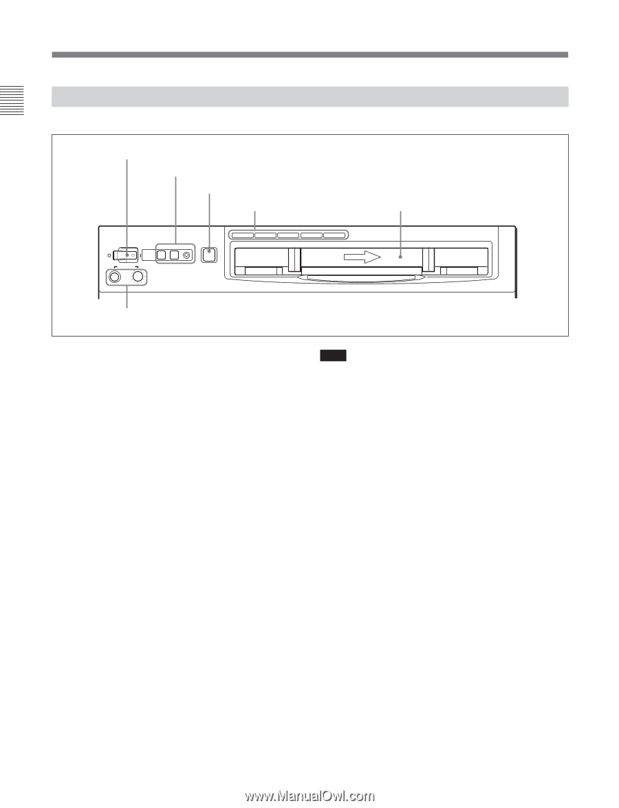
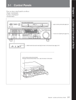
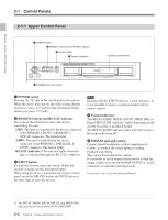
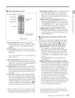
Chapter 2 Location and Function of Parts 2-1 Control Panels 2-1-1 Upper Control Panel 1 POWER switch 2 REMOTE buttons and RS-232C indicator 3 EJECT button 4 Format indicators POWER PHONES REMOTE 1(9P) 2(50P) RS-232C EJECT Z BETACAM/SP BETACAM SX MPEG IMX Digital BETACAM Cassette compartment 5 PHONES jack and control 1 POWER switch Pressing the ' ) ' side of the switch powers the unit on. When the unit is powered on, the audio setting display section (see page 2-5) and the time data/menu display section (see page 2-7) light. 2 REMOTE buttons and RS-232C indicator Press one of these buttons to select the device controlling this unit. 1(9P): This unit is controlled by the device connected to the REMOTE 1-IN(9P) or REMOTE 1OUT(9P) connector. The button lights. 2(50P): This unit is controlled by the device connected to the REMOTE 2 PARALLEL I/ O(50P) connector. The button lights. RS-232C indicator: This indicator lights when this unit is controlled through the RS-232C connector. 3 EJECT button To eject the cassette, press this button. While the cassette is being ejected, this button lights. When using the lower control panel as remote control panel, press the DELETE button and STOP button at the same time to eject the cassette. Note Ejecting with the EJECT button is a local operation. It is not possible to eject a cassette in another unit by remote control. 4 Format indicators The BETACAM/SP, BETACAM SX, MPEG IMX, or Digital BETACAM indicator1) lights depending on the current recording or playback format. The BETACAM/SP indicator lights when the format is Betacam or Betacam SP. 5 PHONES jack and control Connect stereo headphones with an impedance of 8 ohms, to monitor the sound during recording, playback and editing. The control knob adjusts the volume. It is possible to set an internal board switch so that the output volume from the MONITOR OUTPUT L and R connectors is controlled simultaneously. For details, refer to the Installation Manual. ...1) The BETACAM/SP, BETACAM SX, and MPEG IMX indicators do not exist on the DVW-2000/2000P. 2-2 Chapter 2 Location and Function of Parts
-
 1
1 -
2
-
3
-
4
-
5
-
6
-
7
-
8
-
9
-
10
-
 11
11 -
 12
12 -
 13
13 -
 14
14 -
 15
15 -
 16
16 -
 17
17 -
 18
18 -
 19
19 -
 20
20 -
 21
21 -
22
-
23
-
24
-
25
-
26
-
27
-
28
-
29
-
30
-
31
-
32
-
33
-
34
-
35
-
36
-
37
-
38
-
39
-
40
-
41
-
42
-
43
-
44
-
45
-
46
-
47
-
48
-
49
-
50
-
51
-
52
-
53
-
54
-
55
-
56
-
57
-
58
-
59
-
60
-
61
-
62
-
63
-
64
-
65
-
66
-
67
-
68
-
69
-
70
-
71
-
72
-
73
-
74
-
75
-
76
-
77
-
78
-
79
-
80
-
81
-
82
-
83
-
84
-
85
-
86
-
87
-
88
-
89
-
90
-
91
-
92
-
93
-
94
-
95
-
96
-
97
-
98
-
99
-
100
-
101
-
102
-
103
-
104
-
105
-
106
-
107
-
108
-
109
-
110
-
111
-
112
-
113
-
114
-
115
-
116
-
117
-
118
-
119
-
120
-
121
-
122
-
123
-
124
-
125
-
126
-
127
-
128
-
129
-
130
-
131
-
132
-
133
-
134
-
135
-
136
-
137
-
138
-
139
-
140
-
141
-
142
-
143
-
144
-
145
-
146
-
147
-
148
-
149
-
150
-
151
-
152
-
153
-
154
-
155
-
156
-
157
-
158
-
159
-
160
-
161
-
162
-
163
-
164
 |
 |