Sony DVWM2000 Product Manual (Operation Manual 1st Edition (Revised 6)) - Page 136
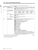
Item number, Settings, B-CAM, CB100, CB75R, PLSBR, MLTBS, 5STEP, WHITE, LN330, Format, Color bars
 |
View all Sony DVWM2000 manuals
Add to My Manuals
Save this manual to your list of manuals |
Page 136 highlights
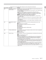
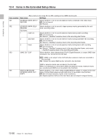
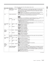
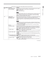
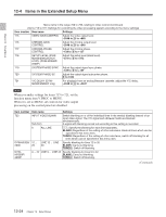
Chapter 12 Setup Menus 12-4 Items in the Extended Setup Menu Menu items in the range 700 to 799, relating to video control (Continued) Item number Item name Settings 707 FORCED VERTICAL The "Y-add" functiona) is normally switched on automatically during jog or variable INTERPOLATION OFF speed playback. This item selects whether or not to force the "Y-add" function off. AUTO : Automatically switch the "Y-add" function on. OFF: Force the "Y-add" function off. 709 CAV LEVEL FORMAT Select whether the analog component input/output should be D-1 or Betacam. (DVW-M2000/M2000P only) Format Color bars Y Video Y Sync R-Y/B-Y D-1 CAV 100/0/100/0 700 mV 300 mV 700 mV Sub-Item Betacam 100/7.5/77/7.5 714 mV 286 mV 700 mV 0 INPUT CAV Select the analog component input format. LEVEL B-CAM : Betacam D1: D-1 1 OUTPUT CAV Select the analog component output format. LEVEL B-CAM : Betacam D1: D-1 710 INTERNAL VIDEO Select the test signal to be output from the VTR's internal test signal generator. SIGNAL GENERATOR OFF: No test signal is generated. (The VTR operates normally.) CB100 : 100% color bar signal CB100 : 100% color bar signal (DVW-M2000P/2000P) CB75 : 75% color bar signal (DVW-M2000/2000) CB75R: 75% color bar signal (reverse) BOW: Bowtie signal PLSBR: Pulse & bar signal MLTBS: Multi-burst signal HSWP: H sweep signal 5STEP: 5-step signal RAMP: Ramp signal SH: Shallow ramp signal RED: Red signal GRAY: 50% flat signal WHITE: 100% flat signal BB: Black burst signal SDI: SDI check field signal NTC7: NTC 7 test signal (DVW-M2000/2000) LN330: Line 330 test signal (DVW-M2000P/2000P) To turn on the internal test signal generator, hold the F1 (VID.IN) button in function menu HOME page for three seconds or more with this menu item set to other than OFF. When the test signal generator is turned on, the display of the VID.IN setting changes to SG. To turn off the test signal generator, press the F1 (VID.IN) button in function menu HOME page again. a) The "Y-add" function is a circuit operation to interpolate the video signal vertically during jog or variable speed playback for the purpose of reducing the vertical movement of the playback picture. (Continued) 12-22 Chapter 12 Setup Menus
-
 1
1 -
2
-
3
-
4
-
5
-
6
-
7
-
8
-
9
-
10
-
11
-
12
-
13
-
14
-
15
-
16
-
17
-
18
-
19
-
20
-
21
-
22
-
23
-
24
-
25
-
26
-
27
-
28
-
29
-
30
-
31
-
32
-
33
-
34
-
35
-
36
-
37
-
38
-
39
-
40
-
41
-
42
-
43
-
44
-
45
-
46
-
47
-
48
-
49
-
50
-
51
-
52
-
53
-
54
-
55
-
56
-
57
-
58
-
59
-
60
-
61
-
62
-
63
-
64
-
65
-
66
-
67
-
68
-
69
-
70
-
71
-
72
-
73
-
74
-
75
-
76
-
77
-
78
-
79
-
80
-
81
-
82
-
83
-
84
-
85
-
86
-
87
-
88
-
89
-
90
-
91
-
92
-
93
-
94
-
95
-
96
-
97
-
98
-
99
-
100
-
101
-
102
-
103
-
104
-
105
-
106
-
107
-
108
-
109
-
110
-
111
-
112
-
113
-
114
-
115
-
116
-
117
-
118
-
119
-
120
-
121
-
122
-
123
-
124
-
125
-
126
-
127
-
128
-
129
-
130
-
 131
131 -
 132
132 -
 133
133 -
 134
134 -
 135
135 -
 136
136 -
 137
137 -
 138
138 -
 139
139 -
 140
140 -
 141
141 -
142
-
143
-
144
-
145
-
146
-
147
-
148
-
149
-
150
-
151
-
152
-
153
-
154
-
155
-
156
-
157
-
158
-
159
-
160
-
161
-
162
-
163
-
164
 |
 |