Sony DVWM2000 Product Manual (Operation Manual 1st Edition (Revised 6)) - Page 162
TIME CODE IN connector 2-18, REMOTE 2 PARALLEL I/O50P
 |
View all Sony DVWM2000 manuals
Add to My Manuals
Save this manual to your list of manuals |
Page 162 highlights
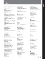
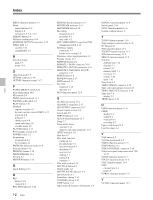
Index Index MENU (function menu) 11-3 Menu control buttons 2-6 display 2-8 operation 2-6, 6-2, 12-2 MIXING button 2-4 Moisture condensation 14-4 MONITOR OUTPUT connectors 2-18 MPEG IMX 1-1 cassette 3-10 compatibility 1-2 N Non-drop frame mark 3-9 mode 11-4 O Operation mode 3-9 OPTION connector 2-18 OUTREF (function menu) 11-7 P PANEL SELECT switch 2-14 Parts replacement 14-6 PB controls 2-6 PB/EE (function menu) 11-3 PHONES jack/control 2-2 PLAY button 2-11 Playback capstan override 4-9 dynamic motion control (DMC) 4-12 jog mode 4-8 normal 4-7 shuttle mode 4-8 speed indication 2-8 variable mode 4-9 PLAYER button 2-12 Power supply section 2-17 POWER switch 2-2 Preparations for playback 4-6 for recording 4-1 PREREAD (function menu) 11-8 Preread editing 5-14 PREROLL button 2-10 PRESET/REGEN 11-4 Preview 5-7 PREVIEW button 2-13 Q Quick Editing 5-13 R REC button 2-10 controls 2-6 REC INHI indicator 2-10 I-2 Index RECINH (function menu) 11-8 REC/ERASE indicator 2-13 RECORDER button 2-12 Recording preparations 4-1 procedure 4-5 time code 4-2 REF. VIDEO INPUT connectors/75Ω termination switch 2-16 Reference signals connection 3-5 for the servo system 3-4 Reference video signal generator 3-3 Regular checks 14-5 REMOTE buttons 2-2 REMOTE 1-IN(9P) connector 2-18 REMOTE 1-OUT(9P) connector 2-18 REMOTE 2 PARALLEL I/O(50P) connector 2-17 RESET button 2-8 REVIEW button 2-13 REW button 2-11 RS-232C connector 2-18 indicator 2-2 RUN (function menu) 11-4 S SC (function menu) 11-6 SDI INPUT connectors 2-17 SDI OUTPUT connectors 2-17 Search control section 2-8 Search dial 2-9 SERVO indicator 2-11 SETUP (function menu) 11-5 Setup 3-7 Setup utility menu overview 13-1 memory stick data operations 13-1 SHIFT indicator 2-8 Shot data 6-7 Shot mark function cueing up 6-6 list operations 6-4 operation menu 6-2 operations 6-3 overview 6-1 reading 6-3 sorting 6-8 writing 6-3 Shot mark section 2-13 SHUTTLE button 2-9 Shuttle mode 4-8 SHUTTLE/VAR indicator 2-9 Specifications A-1 Standalone editing 5-14 STANDBY button 2-10 STOP button 2-11 Superimposed character information 3-8 SUPUTL (function menu) 11-8 Switch panel 2-14 SYNC (function menu) 11-6 System configurations 1-4 T T INFO (function menu) 11-6 Tape transport control section 2-10 TC button 2-11 TCG (function menu) 11-4 TCGSET (function menu) 11-3 TCR (function menu) 11-4 TELE-F (function menu) 11-8 Tele-File attribute data 7-11 clip data 7-3 format 7-12 memory label 7-1 overview 7-1 resume 7-10 undo 7-10 Time Code 4-2 TIME CODE IN connector 2-18 Time code input/output section 2-18 TIME CODE OUT connector 2-18 Time data 3-8 display 2-7 TRIM buttons 2-12 U UMID (function menu) 11-8 UMID display 8-4 output 8-4 overview 8-1 recording 8-2 Upper control panel 2-2 User bit values 4-2 V VAR button 2-9 Variable speed mode 4-9 VIDEO (function menu) 11-5 VIDEO button 2-11 VIDEO CONTROL connector 2-18 Video test signal (setup menu item 710) 12-22 VID.IN (function menu) 11-3 VIN LV (function menu) 11-6 VITC (function menu) 11-4 VITC external sync 4-4 field 3-9 V.PROC (function menu) 11-5 Y YC DLY (function menu) 11-5
-
 1
1 -
2
-
3
-
4
-
5
-
6
-
7
-
8
-
9
-
10
-
11
-
12
-
13
-
14
-
15
-
16
-
17
-
18
-
19
-
20
-
21
-
22
-
23
-
24
-
25
-
26
-
27
-
28
-
29
-
30
-
31
-
32
-
33
-
34
-
35
-
36
-
37
-
38
-
39
-
40
-
41
-
42
-
43
-
44
-
45
-
46
-
47
-
48
-
49
-
50
-
51
-
52
-
53
-
54
-
55
-
56
-
57
-
58
-
59
-
60
-
61
-
62
-
63
-
64
-
65
-
66
-
67
-
68
-
69
-
70
-
71
-
72
-
73
-
74
-
75
-
76
-
77
-
78
-
79
-
80
-
81
-
82
-
83
-
84
-
85
-
86
-
87
-
88
-
89
-
90
-
91
-
92
-
93
-
94
-
95
-
96
-
97
-
98
-
99
-
100
-
101
-
102
-
103
-
104
-
105
-
106
-
107
-
108
-
109
-
110
-
111
-
112
-
113
-
114
-
115
-
116
-
117
-
118
-
119
-
120
-
121
-
122
-
123
-
124
-
125
-
126
-
127
-
128
-
129
-
130
-
131
-
132
-
133
-
134
-
135
-
136
-
137
-
138
-
139
-
140
-
141
-
142
-
143
-
144
-
145
-
146
-
147
-
148
-
149
-
150
-
151
-
152
-
153
-
154
-
155
-
156
-
 157
157 -
 158
158 -
 159
159 -
 160
160 -
 161
161 -
 162
162 -
 163
163 -
 164
164
 |
 |